An AC-Hum touch sensor assembled on a breadboard for test
An AC Hum touch sensor is a very special technique, rarely used for switching applications, because it has a great disadvantage. In order to operate normally, an active AC power line has to be near by. More info about this type of touch sensor, along with other types (including the capacitance method), can be found in the corresponding theory page, how the touch buttons work..
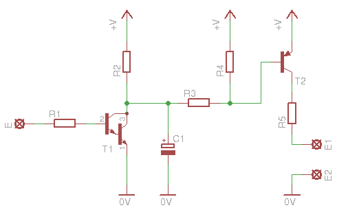
AC Hum touch sensor with momentary make action (Touch button)
If you have already read the corresponding theory about touch sensors, you will not be surprised by the simplicity of this circuit:
As you know, the human body acts as an antenna, which induces the 50 or 60 Hz from near by power lines. When the electrode is touched, the AC signal is transferred through the protective R1 resistor to the base of the darlington pair transistor amplifier. A large electrolytic capacitor connected at the output of this transistor (C1) will smooth the AC signal, same like the smoothing capacitors of a power supply do. The next stage is the switching transistor. I chose to use a PNP type, because the first darlington transistor is connected as an inverting amplifier (worked much better). With this PNP, when the electrode is touched, the load will be activated. Use a NPN to invert operation (for NPN type, emitter and collector are inverted!).
The load is connected to E1 and E2, with E1 being the positive. I should have mark them with L instead, but you get the point. The current limiting resistor R5, must be selected according to the current and the T2 transistor specifications. The one that i use can handle up to 800mA. In case that you connect a relay, this resistor can be totally omitted. Pretty much the same rules are applied, as in the previously-presented circuit (Resistance Touch Button)
The electrode is released
The electrode is touched
Bill Of Materials
Resistors
R1
Resistor 4.7 KOhm 1/4 Watt 5% Carbon Film
R2
Resistor 470 KOhm 1/4 Watt 5% Carbon Film
R3
Resistor 22 KOhm 1/4 Watt 5% Carbon Film
R4
Resistor 100 KOhm 1/4 Watt 5% Carbon Film
R5
Selected according to your load
Capacitors
C1
Electrolytic Capacitor 1 uF 50 Volts
Transistors
T1
BC517 NPN Darlington Transistor
T2
BC327 Switching and Amplifier Applications PNP Epitaxial Silicon Transistor
AC Hum touch sensor with toggle action (Touch Switch)
The previous circuit acts as a momentary touch button. To convert it into an on-off button, i added a Flip-Flop connected as toggle F-F, exactly as i did with the previous circuit (Resistance Touch Button)
The operation is explained in details in the previous circuit, so i will not go through it again. What you need to have in mind, is that, an AC hum touch sensor, is a very special touch sensing method, most of the time not proper for switching applications. I encourage you to read the theory to learn more about it.
The output is OFF
The output is ON
Bill Of Materials
Resistors
R1
Resistor 4.7 KOhm 1/4 Watt 5% Carbon Film
R2
Resistor 470 KOhm 1/4 Watt 5% Carbon Film
R3
Resistor 22 KOhm 1/4 Watt 5% Carbon Film
R4
Resistor 100 KOhm 1/4 Watt 5% Carbon Film
R5
Resistor 220 Ohm 1/4 Watt 5% Carbon Film
R6
Resistor 220 KOhm 1/4 Watt 5% Carbon Film
R7
Resistor 1 KOhm 1/4 Watt 5% Carbon Film
R8
Resistor 22 KOhm 1/4 Watt 5% Carbon Film
R9
Selected according to your load
Capacitors
C1
Ceramic Capacitor 0.1 uF 50 Volts
C2
Electrolytic Capacitor 4.7 uF 50 Volts
C3
Electrolytic Capacitor 1 uF 50 Volts
Transistors
T1
BC517 NPN Darlington Transistor
T2
BC327 Switching and Amplifier Applications PNP Epitaxial Silicon Transistor
@Gleiry usually for the theories i search from the internet and make experiments and tests myself. As for the circuits they are results of my research. If i copy one circuit from a source or if i alter one circuit, i name this source.
Good project,I want to make a replacement for the parts in the second(and first schematics) so I will replace the Flip flop with PIC microcontroler,I will put an digital port on PIC16F628A and any changes of the digital port the microcontroler will note them like +1 in the variable.I want to make an Dimmer for my light bulb :D
This circuit is for educational reasons mainly. Do not use it as a switching circuit. Is not reliable.
For your problem, try again with an ac lamp near you. To operate, there must be an active ac line near by. otherwise, it does funny things.
At 26 January 2011, 15:07:56 user Fung wrote: [reply @ Fung]
I test the circuit Touch button on bread board, 9V battery is used. Since I have no BC517, so 2 BC547 are used instead. When I connect the power, the LED just flashed once.
When I touched the pad E, the LED did not light, that's no action. However when I was breathing out (with humidity) to E, the LED light up for a while. When E is drying, the light intensity of the LED drecreases slowly.
After E is dried, I touch it again, the LED does not light, why?

 Home
Home
 Projects
 Experiments
 Circuits
 Theory
 BLOG
BLOG
 PIC Tutorials
 Time for Science


 Contact
 Forum
Forum
 RSS
RSS


 Reddit this

