The idea of this circuit came to me when i faced the problem itself. I decided to make a project that would check the temperature in my PC box and control 4 fans accordingly (the project worklog is at Automatic 4-fans (120mm) PC-box cooler/regulator + temperature indicator/alarm) . At first, i wanted to use PWM fans (the ones with the 4 wires) so that i could have speed control and rpm feedback simultaneously. But i already had in stock 6 120mm fans with 3 wires. That is when a long story began.
A briefly history
It was just about then that i decided to find a way to control 3-wire fans with PWM and have rpm feedback simultaneously. I have to admit that i visited many forums, but the answer was always the same:
'This cannot be done. If you power a 3-wire fan with PWM, instead of the rpm feedback, you will get the PWM pulses back from the third (yellow) wire'.
A Test circuit, the first that worked perfect, with pure PWM pulses powering the fan and a clear rpm feedback, capable to automatically adjust the speed of the fan at 900rpm
The final version of the circuit in operation with a fan running at 800rpm
I was rather disappointed from this, but i was more disappointed when i discovered how truth that was! Indeed, if you drive PWM pulses on a 3-wire fan, you will get them as feedback from the third wire. There was no possibility to use them as rpm measurements. Also, the PWM pulses caused a kicking sound due to the non-linear torque on the shaft of the motor. Then i did a trick. I put a large 1000uF capacitor across the mosfet that was driving the fan. Out of the sudden, all the problems were solved! The kicking sound did stop! And also, i could finally get clear rpm pulses from the third wire! (Linear DC motor speed controller using a simple PWM switching mode power supply)
Was that a true solution? No, not really. Even though that everything worked perfectly, even though that i could control the speed of the fan and i could also get rpm feedback simultaneously, that solution had a major drawback. What i really had done was to convert the PWM pulses into a switching power supply or something. The voltage across the fan could be changed according to the duty cycle of the PWM. So, when the duty cycle was reduced, the voltage was also reduced, and when the voltage on a fan is reduced, so does the torque and so does the speed.
I was aware of this. I also wrote another circuit article with a 555 PWM fan controller, but within the article i explained that the PWM pulses did actually this: They changed the capacitor across the fet. For me that was a solution and i did not take it any further, until it came up to a disaster! I left a PIC circuit with this 'PWM' fan controller and a precision rpm counter to run for about two months. Then i discovered that, as time was passing, the rpm of the fan was not stable at all. Day by day, the rpm reduced, even with steady duty cycle. I tried to find a logic explanation for this. I suppose that the dust is responsible for this. Then, i run some tests just to find out that in lower speeds, the rpm were dramatically reduced.
But dust was not the only cause for the problem. The system itself had a problem. The low voltage across the fan, did not create enough torque to overcome the dust. You see, the fan, instead of 12 volts PWM, was powered with 6 volts...
Back to the lab, i decided to make a separated fan controller for each of the 4 fans. Each fan would be controlled from a separated PWM generator, and a feedback would be sent back to the PIC. If the rpm of the fan are reduced, the PIC will increase the duty cycle, trying to keep the rpm stable. It did not take me long to make such a controller. Although it did work perfectly, i was not very pleased from the result. I really wanted to have pure PWM to power the fan. This large capacitor was getting on my nerves. But everytime i tried to remove it from the circuit, the PWM pulses annoyingly appeared from the yellow rpm wire...
And then, one afternoon, out of the sudden it just came to me.
'I do not care if the PWM pulses appears on the third wire. I may not be crazy about this, but what the heck. I will use them for my own good!'
The idea
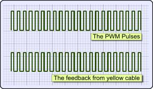
The following drawing shows what happens if you power a 3-wire fan directly with PWM pulses:
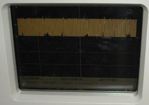
And here is a photo from the oscilloscope showing the output from the third wire. Instead of a clear set of rpm pulses, the PWM appears:
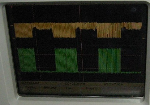
And this is what comes from this pin with the pull-up resistor
The first channel (yellow) shows the feedback! The feedback from the third wire is still the PWM pulses. But this time, there can be seen the rpm puses! After some experiments i discovered that when the true rpm feedback pulse was 0, the pwm pulses had 10 Vp-p amplitude. But when the true rpm pulse was 1 (HIGH), the PWM pulses had been shifted for approximately 6 Volts and the amplitude was about 4 Vp-p. That was enough for me! After a few more tests, i discovered that the output of the fan is capable to drive the CMOS gate with the parallel capacitor, by just pulling the third pin up using an 1K resistor!.
Then i used the 4049 buffer powered with 5V to get a nice 5V signal to drive my PIC. The result is the green channel that can be seen in the above picture! This is just impressive! A series of PWM pulses appear on the screen when the rpm pulse is HIGH, and the pulses are gone (0) when the rpm pulse is LOW!
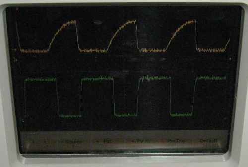
My first idea was to count the rpm pulses themselves during the HIGH time of the real pulse. But that failed to work accurately, because -it may not be seen in the picture- along with the PWM pulses, a lot of parasites come. It was a nice idea but needed a lot of filtering to be done. Then, i added a 4.7uF capacitor between the port input of the 4049 and the ground. Look at the following picture for the result:
The first yellow channel is the input of the 4049, and the second the second green channel is the output. The PWM pulses charge the large capacitor. After a while, when the voltage across it is more than the voltage threshold of the CMOS, the output is driven low. This happens because the 4049 is an inverting buffer. When the PWM pulses stop, the capacitor quickly discharges through the buffer port. Almost instantly, the output is driven HIGH. That's it. I have the rpm pulses right in front of me to use them at my will! You should notice that the pulses that i have right now have a slightly different duty cycle from the real rpm pulses (should have 50% duty cycle) but this is not a problem at all. What i do is to count them for 3 seconds time. Each revolution of the fan provides two pulses. The result of the count must be divided by 2, then by 3 and then multiplied by 60 to get the rpm of the fan:
rpm = Count / 2 / 3 x 60 => rpm = Count x 10
Look at the above equation. The rpm of the fan is ten times the count of the pulses. So, if i count 80 pulses, the rpm is 800, 104 means 1040rpm and 120 comes for the maximum rpm (1200rpm). Very easy e?
The only thing left to do is the control of the fan. Every 3 seconds i measure the RPM. If it is 10 revolutions more or less of the required rpm, then i increase or decrease a duty cycle. The system after some seconds can be completely stabilized to the predefined rpm value.
And what about the kicking sound?
Oh yes, i forgot to mentioned about this. The PWM pulses that i use to power the fan, oscillates at around 48KHz... Even if they do exist, it is impossible for any human to hear it :D
The Circuit
Important!!! Before you make this circuit, please read the section with the title "Unfortunately..."
The following image demonstrates the circuit with the PIC16F88 as the heart of it:
The VDD supply must be 5 Volts regulated. There are two connectors on the right of the schematic. The first one with the 3 pins is for the fan. The positive wire (red) of the fan must be connected to pin 1, the negative (black) to pin 2 and the rpm feedback (usually yellow) goes to pin No 3.
The other connector is the speed selection. You can connect here whatever you want. The way it works is as follows:
If no connection is made, the fan runs at full speed
If the common pin (+5V) is connected to a speed selection pin (1 to 4), the fun runs at a pre-selected speed. In my case, i have program the following speeds (my fan runs max at 1200-1:
Max speed: 1200 rpm
Speed 4: 1100 rpm
Speed 3: 1000 rpm
Speed 2: 900 rpm
Speed 1: 800 rpm
If the common pin (+5V) is connected to the 'Stop' pin, the fan stop running immediately.
The operation
This is a very sophisticated fan controller. It is capable to run a fan with PWM pulses and receive feedback. With this feedback, the circuit will increase or decrease the PWM duty cycle to keep the rpm steady at the pre-selected rpm value.
The circuit is self-calibrated at runtime!
And that was my intention on the first time. The feedback from the fan is translated into revolutions per minute. Then, this value is compared to the desired pre-selected rpm value. The duty cycle then is changed (with large or small changes according the difference) so that the real rpm will be as close as can be to the pre-selected rpm. The measuring Delta is 10 revolutions per minute.
The circuit has A.I.
Do not expect the beginning of humanoids from this circuit. No, the A.I. is much more simpler. Every time the user changes speed, the circuit tries to set the fan to the pre-selected rpm, by changing the duty cycle. Suppose that from speed 5 the user changes to speed 4. The duty cycle for speed 4 is yet to be found from the circuit automation as described before. But this would require a lot of time to be done. So, what i do is to have 4 duty cycle values pre-defined. For example, i have the value 30 for the fourth speed. This value corresponds to a duty cycle. In a perfect world, that would be enough for the fan to run exactly to the desire rpm. But there are many parameters that changes this value day by day: The atmospheric pressure, the heat, the dust, the ball bearing wear and more. So, this value needs to be fixed from time to time.
Here comes the intelligence of the program. When the fan reaches the desired rpm and they are kept steady for at least two measurements taken in a row, then the current duty cycle is compared to a value saved at the EEPROM. There are four positions, each one for a different speed. If the difference is greater than 2 units, then the new value is saved to the current EEPROM position. What is accomplished with this small routine, is to have a 'close' duty cycle value for the desired rpm. So, if the user changes speed from 5 to 4, the PWM duty cycle is directly changed to the previously saved duty cycle value. The fan will be close to the desired rpm and the changes needed from the automation will be accomplished within some seconds.
The Program
Here is the link to download the PIC program complete with all it's components needed. You only need to compile and upload this program to your 16F88 device.
And here is an example of the EEPROM for the program to operate. Positions 0x00 to 0x04 are the duty cycle values that the AI will store and recall. Usually you should not alter them. The next 4 positions corresponds to the speed 4 settings (the 5th is the maximum). The value is the required rpm divided by 8. For example, 800rpm should be saved as 64, because 64 (0x64) hexadecimal = 100 decimal, and that would correspond to 100x8 = 800rpm.
Unfortunately, this circuit has a major drawback. It is not always sure that it will work with every 3-wire fans. I mean, you could use a 4-wire fan and be sure that it works (and also remove the FET as the 4-wire fans have it built-in), but the title talks about 3-wire fans. I tried some other fans. Most of them, with slight modifications in the pull-up resistor and the capacitor did work. But some others did not work. The fans with high rpm (higher than 1200rpm) caused problems when trying to run them at speed lower than 1000 rpm. This is normal though as duty cycle was very low and the tach could hardly send a feedback. Check this out: PC Syatem Health Monitor - A problem
Thanks for the super fast response! The link you provided would actually work perfectly for what I am looking for, as upon further thinking from the first time I wrote, the initial value could be set with one of the resistors on the voltage divider (or the potentiometer). Any increase from the potentiometer would increase the speed, and once the potentiometer is back to it's initial position, the rpms would be once again set to the initial value. Simple! No need for a switch :) Awesome circuit and design! I will take a look at the code for the circuit in the link. Thanks again!
Hi Dave,
Of course you can have a potentiometer. Take a look at this:
http://pcbheaven.com/circuitpages/PWM_3_Wires_Fan_Controller_with_RPM_feedback/
The potentiometer in this design writes directly to the Duty Cycle register. You need to change this and instead, you will update the speed register with the potentiometer value. The switch will actually bypass all values. Easy to do as you may take ideas from bout circuits, you need to do some programming labor though.
I am wondering if it is possible to instead of having preset speeds, could you have a potentiometer to control the speed? Or even better, have a set initial speed of 800rpm until a switch is closed, activating the potentiometer circuit for increasing the speed above the initial 800rpm set point? Of course, once the switch is opened, the rpm would then again be set to the initial set point of ~800rpm
This is an excellent circuit, and intelligent design!
I was afraid that you might run into problems when you moved on to a different fan model but I\\\'m not convinced that the issue was just frequency. I suspect that the new fan just does not provide as clean a signal during the power off cycle.
By the way, I still believe that the tach circuit is being powered by counter EMF generated by the motor during the power off cycle. The circuit has to be getting its enedgy from somewhere.
I went ahead and took a fan apart out of curiosity. It has a single 4 leg component that does everything including the hall effect / tach. Also, it's too small to have any type of filtering, so my "assumption" that the tach pulses are carrying through has to be wrong. Maybe my drive frequency is low enough that once I cross a certain speed threshold the scope is synching on and only displaying the tach output. I need to chase down a second O'scope probe, sync on the PWM feeding the motor and use channel 2 to see what's really going on.
I still plan on building a version of your circuit but it will be at least a few of weeks now. I'm working on a design for a new temperature controller that will work in heat or cool mode and will switch up to 18 Amps at 120 VDC.
I really like the fact that you share your progress with us. I understand that you cannot share the project. No problem. Maybe when you make a project private for yourself.
I re-looked at the pulse trail from the tach output. The signal is a mix of PWM and tach. At lower RPMs the tach is being over-ridden with PWM signal but at higher RPMs its a pure tach output. My best guess is that the tach circuit has a power filter that\'s riding through the off periods but that\'s just a guess. I may disassemble one & see if the controller is made of discrete components. If so then I can map out the circuit and know for sure.
I was able to raise the floor 4V with the diode idea then I re-thought - why am I doing it this way when I can bias the power transistor so that it does not shut completely off? So I removed the diodes & biased the power transistor so that at the PWM shutoff cycle, 4V was still applied to the motor.
But even with the 4V minimum applied across the motor, the tach output acted exactly the same. And at 4V bias, the PWM circuit won\'t run the motor slow enough for my application. In other words, I\'ve backed myself in the corner with the bias idea.
Next week or so I\'ll move the drive transistor to the ground side of the motor and try to duplicate what you have done. Like I said earlier, we all learn from each other.
Ill modify my circuit sometime this week or next weekend and will let you know how it works. Ill also send you a picture of the Oscope screen. My scope isnt near as nice as yours is but Im an old analog guy and its an old analog scope.
If we move to a version of your circuit, Ill still need an inverter or clamp to limit the tach output to 5V because I suspect that the tach pulse will be below 3V during the PWM off cycle. It would be a shame to use a 16 pin inverter just for this, maybe Ill do something simple with a transistor and few resistors.
I apologize but I wont be able to show you the whole design its propriety. Even the blank card and assembled circuit on the web site arent what we are using they are very early prototypes. We are running a PWM controller at audible range but have found a way to soften the kicking sound until you cant hear it. I will say that we had to switch from a power FET to a power bipolar transistor and the transistor is switching the + supply to the motor.
I like the idea with the zener very much. I will give it a try one day. In case you try it first, i would be happy to host your circuit/project. btw, i would be happy to host ANY project/circuit/blog entry you may.
As for the fan tacho, when the FET is off, it does not supply any voltage. I use high frequency for the supply of the fan, which i get back from the feedback only when a positive pulse should arrive from the tacho. When the fet is off, the feedback is off as well. The trick is the 47uF capacitor that gives me a reasonable feedback, by smoothing the high frequency pulses. But i will get some other brands and try it. (i have test it with a 120mm Cooler Master and an 80mm Akasa).
No, a parallel capacitor acts like a filter and averages the voltage down. That's why the fan stalls - it sees only the averaged lower voltage. I'm thinking something more like a zener or diode stack across your MOSFET that will handle the fan current. This way, when the FET is off the fan sees the line voltage minus the zener drop and when the FET is on the motor sees the entire line voltage. For example, with a 12V rail and 9V ZENER your PWM circuit would be driving the motor with 12V, 3V, 12V, 3V, etc.
The ZENER voltage would be chosen based on whatever voltage is needed to drive the fan at minimum speed with good starting torque. In other words, you'd have to experiment to make sure that the ZENER voltage was high enough, reducing the fan voltage low enough to guarantee that even at low speed you have enough PWM "on time" to eliminate stalling.
By the way, I believe your circuit works because the counter EMF supplied by the motor when the FET is off is supplying the tach curcuit with enough for an output. This is also why I believe it may not work with all fan motors. Some may be designed in such a way that the counter EMF is absent.
If i got it right, you say that instead of PWM pulses, to change the voltage across the fan... If so, this can be easily done by adding a parallel capacitor to the mosfet, like this circuit:
http://pcbheaven.com/circuitpages/PWM_Fan_controller_using_a_555/
This solution worked, but the fan stalled very easily (due to the lack of torque) and the rpm is not so stable as may expect.
I have not test with many fans this circuit. With the fans that i have it works. Of course, the PWM duty cycle needs to be changed when i use 120mm or 80mm fans, but this is straight-forward. It does NOT work with 4-wire fans though. If you have something in mind like some kind of fan that you suspect it wouldnot work, please tell me about it. I'm very interested in this.
After re-reading your article, doing some research on 3-wire and 4-wire fan standards and reviewing what I've done so far, I believe that your solution is an excellent design but its also dependent on how the designer implimented the 3-wire standard. In other words, your solution works on the fans you experimented with but there is no guarantee that it will work on someone elses fan.
I wonder if the solution is a PWM design that instead of turning the drive voltage on & off, switched the drive voltage between 100% and 30%? In other words at 15%, the PWM circuit would switch 100% of the drive voltage 15% of the time and 30% of the drive voltage 85% of the time? This may give the hall effect sensor and supporting circuit enough to reliebly produce an RPM signal.
No, I use a 3 wire fan. I have read a lot about how the PWM signal over-rides the RPM out and did not bother verifying myself. Then I went ahead and monitored the tach output with a scope and initially saw nothing. This was confusing because I expected a broken signal - I assumed a bad fan and went on to another one with the same results. So, since the signal was essentially ground, I added a pull-up resistor and suddenly had something. I expected a pulse train broken up by the PWM but I don't see this.
The issue may be that my drive signal is low enough frequency that I am syncing on only the RPM signal when it is there. In other words, I need to connect the second channel and synch on the main power PWM signal while monitoring the tach output.
I guess I just need to build your circuit and experiment!
I would be interested in your new code - we all learn from each other.
Here's the product:
www.stir-plate,com
It's currently in production with an analog PWM circuit and it works very well, but it has no feedback loop. Customers are using it to grow yeast and as the yeast slurry gets thicker the motor slows down. I've experimented with analog feedback loops and have one that works but I wonder if its finally time to go digital.
Hi Tom,
I suppose you use 4-wire fan am i correct? This is a PWM driven fan made for this purpose. In that case, you ca 'lighten up' the circuit a little bit more, because this circuit is made for 3-wire fans (normally not PWM driven). The 4048 buffer as well as the C1 and C2 capacitors can be omitted. The R6 is a pull-up resistor, very important to be used. The fan tacho will sink the current from r6 and generate the logical LOW. The duty cycle of the fan is 50%, and (for my fans) the tacho sends 2 pulses per revolution (with 50% duty cycle). I suppose all fans send the same signal, i am not sure though. As you describe, the same happens with you fans.
In my program, you can add more speeds by adding bytes to the EEPROM (see subroutine LoadSpeedCenters'). In my configuration, i uses EEPROM positions 0 to 5 for the 8 speeds (the rpm divided by 8 eg 800rpm= 0x64), and from 0 to 4 the approximate duty cycle. This value, is an approximate number of the duty cycle when the user requests a speed change. The fan goes to this duty cycle and then self-regulates. The value is saved back to the eeprom.
Trying to change the above code will mess you up. I suggest you 'd better write you own code, and use portions of mine. You should use for example from 'Mainloop' up to 'ReadFanSpeed'. This is the self-regulation routine.
Luckily, the very next project i prepare (actually is ready and i have it under test) is the same self-regulation routine, with I2C protocol to select whichever speed you like ( i test it currently with automatically changing speeds from 600 to 1200 with 20rpm step->25 speeds). Be patient and within this week, i will publish it.
A am running a 80 mm fan now as low as 200 RPM with no problem and I am using a PWM circuit to drive the fan. Problem is, I need to keep it at the speed I set it at. Also, I need more than 4 speeds - I really need 10 speeds.
I'm switching the + side of the power supply and I did some research since the last message. With a 10K pull up resistor I get a reliable pulse train from the tack output even with the PWM drive. The only thing I can figure is that the fan is switching the tach lead to ground 50% of the time and the pull-up resistor is bringing the signal back up when the lead is not pulled to ground. Any input on this?
Helo Tom,
First of all, the code is indeed open source. Use it freely.
As for the speed control, for normal 12V DC fans usually for PC cooling, it is almost impossible to run lower than 600rpm constantly. They will stall for sure. They are not designed to operate so slow.
What details you need to know about the code? How can i help you?
At 18 January 2010, 20:15:01 user Tom wrote: [reply @ Tom]
Can I assume that since you posted this on the net that it's open source? I'm asking because this looks like almost what I need. But I need a circuit that will control more fan speeds starting at 100 RPM, then 200, 300, 400, 500, 600, 700, 800, 900, 1000. I need to set an airflow constant, not for cooling, for another process control.
I fully understand your circuit and could reverse engineer your code but I I'm not a PIC programmer. I wonder if you could provide more details about your code?

 Home
Home
 Projects
 Experiments
 Circuits
 Theory
 BLOG
BLOG
 PIC Tutorials
 Time for Science


 Contact
 Forum
Forum
 RSS
RSS
 PIC Fan automatic controller

 Reddit this

