
|
 Home Home
 Projects Projects
 Experiments Experiments
 Circuits Circuits
 Theory Theory
 BLOG BLOG
 PIC Tutorials PIC Tutorials
 Time for Science Time for Science
|
| ||
|
22 October 2011 Author: Giorgos Lazaridis Tiny LED Debugging Board for Breadboard PrototypingIf you happen to work with microcontrollers or other digital ICs, then you have certainly face a situation where you need urgently 8 LEDs with 8 resistors for a test or other debugging purposes. And it is this time where things get nasty: You are in a hurry because you want to see the results, connecting the LEDs is totally boring, you need also 8 resistors, not to mention the wires, and then, the LEDs themselves are thick and usually won't fit in 8 breadboard rows... You know what i mean. Therefore, i decided to make a tiny board with SMD LEDs and resistors pre-wired to save the day. The circuit The first idea was to make an 8-LED board, because usually data come in 8-bit packets. But since i work with PIC microcontrollers, i do know that PORT pins usually come in sets of 4 pins, excluding PORTB which may come with all the pins in series. Therefore i decided to make boards with 4 LEDs. The idea is that the board will be small enough, so that another board will be able to sit right next to it. This way, both 4-series ports and 8-series pots will be covered. The schematic is ridiculously simple: 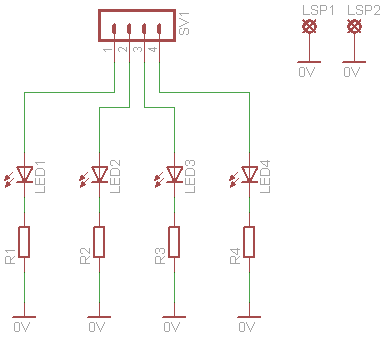
No comments needed... The PCB It was not difficult to design the PCB small enough, since i will be using SMD parts only (excluding the connectors of course). Here is how the PCB looks like: 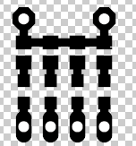
And here is the EPS file of the PCB:
Then i began the PCB development:The PCB
Soldering the parts I will be using size 0805 SMD parts for the resistors and the LEDs. The connectors are simple 0.1' pitch headers:
Powering the boards I use 220 ohms resistor for the LEDs. This way, they will normally operate both for 3.3 and 5 volts supply. The maximum current they draw do not exceed the 20mA @ 5 volts, so the PIC will is safe. 
These boards are Common Cathode, since all LED cathodes are connected together to the common (Com) connector. A Common Anode board can be made if all LEDs are revered. Comments
|
|
 Contact Contact
 Forum
Projects
Experiments
Circuits
Theory
BLOG
PIC Tutorials
Time for Science Forum
Projects
Experiments
Circuits
Theory
BLOG
PIC Tutorials
Time for Science
 RSS RSS
Site design: Giorgos Lazaridis © Copyright 2008 Please read the Terms of services and the Privacy policy |
 PCB EPS file


 Reddit this

