| This project is not completed yet - Last update: January 27, 2013 |
PAGE 2 of 8 - Speed Indicator Panel
[ Speed Indicator Panel ]
Another fantastic modification was the speed indicator panel.....
I wasn't completely sure of the combination with the colors i was going to use.
My motobike as you see is light-blue.So the first color that was candidate was the blue, and the second one
was the (cold) white.
After few experiments i did, i ended that the cold white was obviously the best color that suited the panel.
| | 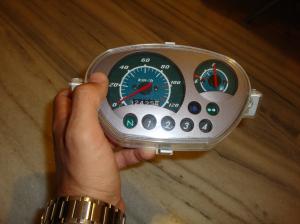
The Speed indicator panel. (Notice i have painted the needles. Sun had made them fade out.) | |
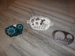
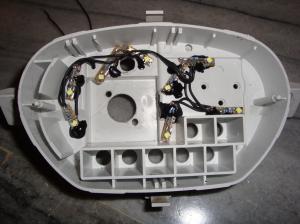
So when i disassembled the panel, for my good luck again, i observed that the holes that panel have for the bulb gears, are rounded were i consumed that 10mm leds would fit on these holes..... So i bought 10mm white leds for the gears and some smd leds for the panel backlight.And VOILA!!!! I was correct. The rounded 10mm Leds were perfectly fitted on the holes with a little bit help from a drill with 9.5mm diameter so that the leds would go into the holes cuneated.
 |
 |
| The disassembled speed indicator panel. |
The way i glued the smd leds for the backlight.(Observe the holes.) |
| | 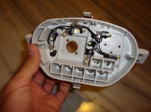
Another view with the 10mm Led. | |
Then i decided that it would be a nice idea of developimg a pcb to mount the leds and the controller on it.
So i carefully designed the pcb, after i had made my measurements....
And believe me it wasn't so easy to alligh the leds to the panel.
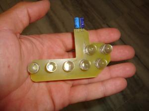
(I did three of them the first had wrong allignment, the second one had error with the transistor i used npn instead of pnp, and the third one was my last without errors.) Here are the results of the final pcb....
 |
 |
| The front side of the pcd. (Notice that there is nothing on the front because it has to go firmly to the panel.) |
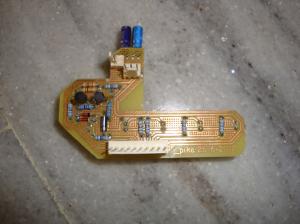
The bottom side of the pcb. (Notice the connectors.) |
 |
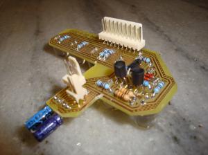 |
| Another look of the bottom side. |
A Closer look of the bottom side. |
The connectors on pcb's bottom are for:
The 3 pin connector connects the LM7806 with the pcb (I had to fend it off because it should be placed on a heatsink.)
The 2 pin connector connects the backlight smd leds, and also an extra 10mm led for panel's backlight.
The 10 pin connector has the connections with the gears,the flasher,the big scale lights,and the power supply...
 |
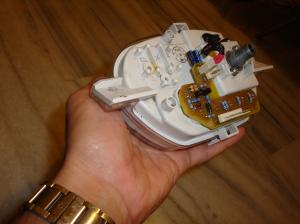 |
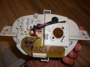
| The pcb mounted on the panel. (Notice the connection of the leds with the extra one.) |
A different angle of the pcb mounted on the panel. |
You can download the file below, which includes the schematic and the board in eagle format.
 |
 Download file Download file
Speed Indicator Panel File in Eagle format .sch and .brd |
Bill of matelrials
| | Bill of materials | | | Resistors | | R1 | Resistor 130 Ohm 1/4 Watt Carbon Film | | | R2 | Resistor 130 Ohm 1/4 Watt Carbon Film | | | R3 | Resistor 130 Ohm 1/4 Watt Carbon Film | | | R4 | Resistor 130 Ohm 1/4 Watt Carbon Film | | | R5 | Resistor 130 Ohm 1/4 Watt Carbon Film | | | R6 | Resistor 130 Ohm 1/4 Watt Carbon Film | | | R7 | Resistor 130 Ohm 1/4 Watt Carbon Film | | | R8 | Resistor 1 KOhm 1/4 Watt Carbon Film | | | R9 | Resistor 1 KOhm 1/4 Watt Carbon Film | | | R10 | Resistor 10 KOhm 1/4 Watt Carbon Film | | | R11 | Resistor 10 KOhm 1/4 Watt Carbon Film | | | | Capacitors | | C1 | Electrolytic Capacitor 10 uF 35 Volts | | | C2 | Electrolytic Capacitor 10 uF 35 Volts | | | | Diodes | | D1 | 1N4148 Switching Diode |  | | D2 | 1N4148 Switching Diode |  | | D3 | 1N5819 Diode 1A 40V Schottky Rectifier | | | | Transistors | | TR1 | BC558 PNP Epitaxial Silicon Transistor | | | TR2 | BC558 PNP Epitaxial Silicon Transistor | | | | IC's | | IC1 | 7806C Positive Voltage Regulator |  | | | Led's | | LED 1-7 | 10mm Rounded White Leds | | | LED 8-15 | Smd White Leds | |
Comments
At 5 March 2015, 23:49:39 user Stentor wrote: [reply @ Stentor]I still don't get it, as my bike has 4 oem cables: gnd(black) green and 2yellow ones. I made the led "bulb" according to your idea (thans again) but driven it with a 10w led driver and not your driver, but this way i only have 1 beam, cause could not figure out how connect 4 cables to 5 jumpers (ok the two are the led out) lol.
Thanks anyway. You are very helpful.
At 19 February 2015, 11:22:31 user Panagiotis Kalogeris wrote: [reply @ Panagiotis Kalogeris]If you open the schematic and the board files which are listed below it will be more clear to you.
There are 7 pins
2 for the input 12-14,5v (Bebause of the alternator)
2 for the led and
3 for the selection of the beam (High,Low Half pin is the common).
Regards Panagiotis
At 16 February 2015, 16:54:48 user Stentor wrote: [reply @ Stentor]No that idea was also great.
My question was on the connections from the 3 oem cables (earth,high,low beam) to the pcb pins, as far as i can see, there is an extra input on the board, have you driven a new 12v cable or have i understood wrong?
Thanks in advance and for the quick reply.
Respect
Dimitris Stentor
At 12 February 2015, 18:17:08 user Panagiotis Kalogeris wrote: [reply @ Panagiotis Kalogeris]Hello Stendor and thank you for your good words....
If i have undrestand you correctly, you mean that... "why not to place the led on the yamaha's bulb socket? " If is that so, then i will answer you that you will face a ploblem which is blinding other drivers.
With the aluminium rod i used i have made a 45 degrees corner approximately and you avoid blinding other drives....Please if you meant something else post again.
Regards Panagiotis
At 11 February 2015, 19:59:19 user Stentor wrote: [reply @ Stentor]Amazing work. I have the exact same model, but i have a silly question
Since at the oem bulb socket, are 3connections (low,high,earth), have you driven a different,new one for the Vin? Would'n be a way to use only the oem connections?
Thank you
At 10 December 2013, 0:30:25 user Panagiotis Kalogeris wrote: [reply @ Panagiotis Kalogeris]Nevermind..... Glad to learn something that i didn't know!
So.... the more the better!!! :-)
At 1 December 2013, 6:37:44 user astral_mage wrote: [reply @ astral_mage]i hate to correct u there but leds now have an average lifespan of 200,000 - 300,000 hour lifespan
At 19 November 2013, 23:09:21 user Panagiotis Kalogeris wrote: [reply @ Panagiotis Kalogeris]Hello John sorry for the late reply well try to find transistors with the same characteristics....Its not critical the type of the particular transistor.The driver transistor is the transistor that you must select carefully...I'am here to help you as much as i can.
Regards
At 10 November 2013, 23:25:10 user John wrote: [reply @ John]Great I couldn't understand the jp thank you!!!
Another question about the transistor , I saw you used two types one with plastic cover (TO92) and one with metal (TO18). Were they 2N2222 and BC107 or something else (I do not know if there is a difference)?
I took the advice of Kam and yours and I will use buck convectors, so I believe the dissipation will be less so I think the TO92 will be nice.
The resistances you choose are rated 1/2 watt?
P.S. I will have more question later!!!
At 9 November 2013, 9:23:45 user Panagiotis Kalogeris wrote: [reply @ Panagiotis Kalogeris]Hello John!
Well Jp1 is the input of the circuit.Is where you connect the power from your battery (Jp1 pin1 pin2-).
Jp2 is the output where you connect the led (Jp2 pin1 pin2-).
And finnaly Jp3 is the selection switch for the 2 scales of the led brightness.
So there you will have to connect the switch on your left hand where you can select the 2 scales.If you wire the middle one with one of the two resistors you will notice the brightness changes according the value of the selected resistor.
Yes for the rear led i used 3w where i have it working on half when i do not press break....
I have also noticed your observation for the front led. I was thinking of placing a small fan for cooling it down.But after few experiments i ended that it gets very hot on the big scale where is not always "on".My considarations wasn't for the plastics but for the led itself (Reducing his life dramatically)the incadescent lamp was getting much hotter that the led's heatsink.Also remember that if you place a fan you can increase the wattage of the led.Also if you are planning to add a fan don't forget to make some big holes to the surrounding plastic.
"Look to the picture with the comment " The heatsinks i used taken from a broken tv. (Notice the one mosfet with the 7806.)""on led driver page.
At 25 October 2013, 11:14:26 user John wrote: [reply @ John]Really nice!!!
I am trying to do something like yours to test it but at your Led Driver Pcb I cannot understand where to connect jp1,2,3.
I can understand that this pcb with the 3.3 and 1.2 ohm resistors are for the front light of 10w.
For the red rear light did you use 3watt led?
The front led heatsink is it getting very hot, I am wondering about the plastics around the light.
Thank you
P.S. I m waiting the rest of the worklog!!!
At 4 March 2013, 8:07:57 user Panagiotis Kalogeris wrote: [reply @ Panagiotis Kalogeris]Hosea i am currently working on it i will post it when it will be finished and of course tested.
Its in a "beta mode" right now... :-)
At 4 March 2013, 8:01:27 user Panagiotis Kalogeris wrote: [reply @ Panagiotis Kalogeris]I will post the circuit diagram as soon as possible...( i must draw it first :-) ) As for the high and the low beam here's what i did....For the low beam, i drive the led with current consumption around 300ma and for the high beam i drive the led with current consumption around 900ma.Believe me it acts like a high beam because of the lumens that produces and of course without blinding other drivers......
At 28 February 2013, 18:23:12 user Matheus Lopes wrote: [reply @ Matheus Lopes]That rod idea is genial. But how would you use the high and low beam?
At 28 February 2013, 13:44:21 user Hosea wrote: [reply @ Hosea]the modifications are very impressive but looking forward to see the circuit diagram of the alarm |
|
 HOT in heaven! HOT in heaven!

|
|

 Home
Home
 Projects
 Experiments
 Circuits
 Theory
 BLOG
BLOG
 PIC Tutorials
 Time for Science
 Contact
 Forum
Forum
 Projects
 Experiments
 Circuits
 Theory
 BLOG
BLOG
 PIC Tutorials
 Time for Science
 RSS
RSS