
|
 Home Home
 Projects Projects
 Experiments Experiments
 Circuits Circuits
 Theory Theory
 BLOG BLOG
 PIC Tutorials PIC Tutorials
 Time for Science Time for Science
|
| ||
|
22 March 2009 Author: Giorgos Lazaridis The CapacitorWhat is a capacitor A capacitor is a device that has two metal plates placed in parallel. These plates are galvanic isolated (no means of electrical contact between them). Between these plates, there is the dielectric material. This material can be anything like air, oil, paper, ceramic, mica, as long as it does not create electrical contact. A rough drawing of the inside of a capacitor is as follows: 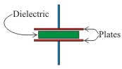
Here are some common symbols of capacitors used in drawings: 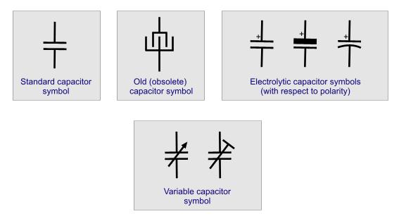
How does a capacitor work Suppose we have the following circuit: 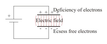
When voltage is applied to it's plates, an electric field is generated between them causing a significant difference of free electrons to develop between it's plates. Free electrons are forced to gather on the negative connected plate and from the positive connected plate free electrons are taken away. This is the representation of the charge effect of the capacitor. The greater number of electrons polarized, the greater field generated and the greater charge of the capacitor. When the capacitor is disconnected from the power supply, it will remain charged. An ideal capacitor would remain charged indefinitely but in practice this is not possible due to a slight leakage current that is caused between it's plates. The capacitor works as a load and as a source on a circuit. This is shown in the following diagram: 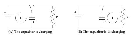
In case (a), the capacitor is connected to the power source. During it's charging time, it works as a load drawing current from the source until it is completely charged. In case (b), the capacitor works as a source. It discharges it's electrons to the load. Notice the direction of the current in each case. Calculating capacitance The amount of capacitance that a capacitor can achieve depends on three characteristics. First of all the size of the plates. The bigger the plates, the bigger capacitance. The distance of the plates is reverse proportional to the capacitance. The longer the distance, the smaller the capacitance. Finally, the type of dielectric material between the plates. Putting it all together, the formula for calculating the capacitance is as follows: C = e x A / D where e is the dielectric material standard, A is the area of the plates and D is the distance of the plates. Following is a table with the most commonly used dielectrics and it's dielectric constants.:
Charging and discharging a capacitor Capacitors do not have stable resistance during time. The type for calculating the current through a capacitor is given for instantaneous current and it is as follows: i= C x (dv / dt) where C is the capacitance in Farads and dv/dt is the instantaneous voltage change in time. Looking this formula we can see that the factor 'time' takes place in calculation. This is because the electrical effects of a capacitor change over time during charge and discharge. Take a look at the following circuit: 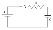
When the circuit is closed, the capacitor starts to charge through the resistor. The capacitor will be fully charged after an amount of time. We define as time standard T the time that the capacitor needs until it is charged to the 63.3% of it's final value V. To calculate this time we use the following type: T=R x C The following diagram shows the change in voltage on the capacitor's pins during time: 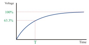
It is clear that voltage on the capacitor constantly changes. This means that the voltage drop on the resistor will constantly changes and thus, due to Ohm's law, the current in the whole circuit will constantly change. Is it possible to charge 100% the capacitor and how much time would it need? The answer is no. In our example, the capacitor is 10iF and the resistor is 1Mohm. This gives us a time standard of: T = R x C = 1 x 10 [106 x 10-6] = 10 secconds. This means that the capacitor will be charged at 63.3% of the power supply in 10 seconds. If the power supply is 10Volts, after 10 seconds the capacitor will be charged at 6.3volts. Another 3.7Volts (10-6.3) remains to be charged for 100%. After 10 more seconds the capacitor will have 63.3% of 3.7 volts charged which means another 2.3 volts more giving a total of 8.6 volts. Another 1.4 volts remain to be fully charged but after 10 more seconds it will have 63.3% of these 1.4 volts and so on. The capacitor will never be 100% charged no matter how much time it passes. Discharging a capacitor is more or less the same. With the same time standard, the capacitor discharger every time 63.3% of it's voltage.  Current leads to voltage If we connect a resistor directly to a power supply, the maximum current rate of this resistor would be achieved immediately. This does not happen with a capacitor. A capacitor increases its voltage (and thus decreasing it's current) gradually. The current would start from it's maximum rating and decreases gradually in opposition to the voltage that starts from 0 and increases gradually. This means that in a capacitance circuit: Current leads to voltage Energy storage When a capacitors is charged, it has store an amount of energy. you could consider a capacitor as a kind of battery that charges and discharges. The amount of energy that can be hold is calculated from the following form:
Capacitors in DC circuits  Ex. 3 A capacitor smoothing the output of a Power Supply Unit  A capacitor connected in a DC circuit  Ex. 1 A noisy power source  Ex. 2 A noisy power source smoothed by a capacitor A capacitor connected on a DC circuit will not allow any current to flow within the capacitor. At first, when a discharged capacitor is connected to a DC circuit(A), if will follow the charging procedure as described before. Then, when the capacitor is fully charged, it will operate as a circuit break. The charged capacitor can be connected to a load (B) and then following the discharged procedure it will discharge it's load over the connected load. In DC circuits, a capacitor could be connected across the leads of a noisy power source, as for example the charger of a car (Ex. 1). The waveform from the generator is not a straight line (like the ideal DC voltage). A large capacitor will significantly smooth the ripples (Ex. 2). Another common application for a capacitor in DC circuits is the smoothing of a DC power supply (Ex. 3). The output of the transformer is rectified from the diodes, but the output signal is not smoothed. Large capacitor(s) are connected across the output of the rectifier. The capacitor will smooth the sin waved output. The more capacitors in parallel are connected, the smoother the output of the PSU. Capacitors in AC circuits A capacitor connected to an AC power source, operates somehow as a resistor. A basic difference is that the capacitor's resistance depends on the frequency of the source. The capacitors resistance is so called 'Impedance' and is calculated from the following formula:
Where F is the frequency in Herz (Hz) and C the capacitance in Farads. The above formula explains why the capacitor operates as a circuit break in DC circuits, where F=0 Hz. Capacitors are used in AC circuits for many different purposes. They are common components of filters, oscillators, amplifiers, etc.  A capacitor will cutoff DC voltage A very common application for a capacitor is the DC voltage cutoff. A capacitor will have some resistance to AC power, but will have infinite resistance to DC power. So, a capacitor connected in series with a circuit will allow only the AC power to cross. A capacitor is usually combined with other components such as resistors, inductors and diodes to perform multiple tasks. Leakage Even though a capacitor's plates are insulated from each other, there is a small amount of 'leakage' current between its plates. This current is generally insignificant but will cause a capacitor to slowly discharge with no external circuit path between the capacitor's leads. Thus, a charged capacitor will not maintain it's charge infinite. Relative pages Comments
|
|
 Contact Contact
 Forum
Projects
Experiments
Circuits
Theory
BLOG
PIC Tutorials
Time for Science Forum
Projects
Experiments
Circuits
Theory
BLOG
PIC Tutorials
Time for Science
 RSS RSS
Site design: Giorgos Lazaridis © Copyright 2008 Please read the Terms of services and the Privacy policy |


 Reddit this

