Home     Contact     Projects     Experiments     Circuits     Theory     BLOG     PIC Tutorials     Time for Science     RSS     Terms of services     Privacy policy  
   
 Home      Projects     Experiments     Circuits     Theory     BLOG     PIC Tutorials     Time for Science   

23 December 2009
Author: Giorgos Lazaridis
The Schmitt Trigger


History

The Schmitt Trigger was first invented from Otto H. Schmitt in the 1934. By that time, Otto Schmitt was a student. In the year 1937, he published his invention in his doctoral. The name he gave was "thermionic trigger"


Symbols

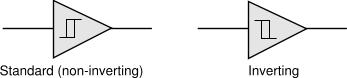
There are basically two symbols for the Schmitt Trigger. The symbol is a triangle with an input and an output, just like the one used for the non-inverting buffers. Inside there is the hysteresis symbol. Depending on the type of Schmitt Trigger, inverting or non-inverting (standard), the hysteresis curve sign differs.


What is the Schmitt Trigger?

The Schmitt Trigger is a type of comparator with two different threshold voltage levels. Whenever the input voltage goes over the High Threshold Level, the output of the comparator is switched HIGH (if is a standard ST) or LOW (if is an inverting ST). The output will remain in this state, as long as the input voltage is above the second threshold level, the Low Threshold Level. When the input voltage goes below this level, the output of the Schmitt Trigger will switch.

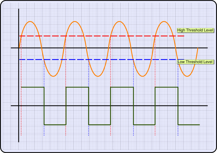
The HIGH and LOW output voltages are actually the POSITIVE and NEGATIVE power supply voltages of the comparator. The comparator needs to have positive and negative power supply (like + and -) to operate as a Schmitt Trigger normally. The following drawing shows how a Schmitt Trigger would react to an AC voltage input:


The orange line is the AC input. The horizontal RED line indicates the High Threshold Level, while the BLUE horizontal line indicates the Low Threshold Level. The green line is the output of the Schmitt Trigger. When the input voltage level goes above the High Threshold Level, then the output of the ST goes High. When the input voltage level goes below the Low Threshold Level, then the output of the ST goes Low. This is the basic operation of a Schmitt Trigger.


Schmitt Trigger circuits
The simplest Schmitt Trigger using OP-Amp

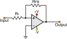
The most simple Schmitt Trigger circuit is implemented with a comparator with a positive feedback. Look at the following circuit:


When the non-inverting input (+) is higher than the inverting input (-), the comparator output switches to the POSITIVE voltage supply. On the contrary, the non-inverting input (+) is lower than the inverting input (-), the output switches to the NEGATIVE voltage supply.

The inverting input (-) is grounded, so someone would expect that the turn-on and off point would be the ground (0). The function of the ST comes from the feedback resistor RFB. When for example the output of the comparator is to the POSITIVE voltage supply, then the non-inverting input has through the RFB this voltage! The same happens when the output is to the NEGATIVE power supply.

The voltage needed to switch the output of the comparator must be above or below zero (ground), according to the POSITIVE and NEGATIVE power supply and according to the resistors RI and RFB. More specific, the formula to calculate the threshold voltage is:


VTHRESHOLD = VSUPPLY x RI
RFB + RI

So, if the output is to the POSITIVE voltage, the required negative voltage that must be applied to Vin is:


VINPUT <= - VTHRESHOLD

If the output is to the NEGATIVE voltage, the required positive voltage that must be applied to Vin is:


VINPUT >= VTHRESHOLD

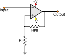
The above circuit is non-inverting Schmitt Trigger. It can be easily converted into an inverting Schmitt Trigger as follows:


The same formula is used to calculate the threshold level. But the output of this circuit is inverted in comparison to the previous one. When the input voltage is above the High Threshold Level, the output goes LOW.

These are the most basic Schmitt Trigger. The threshold voltage is an equal offset from the center of the POSITIVE and NEGATIVE power supply (usually this is 0). Thus, we can call it "symmetrical Schmitt Trigger". I have include a Symmetrical Schmitt Trigger calculator in the Dr.Calculus page. Do not forget to visit and try it!


Relative pages
  • Dr.Calculus: Non-symmetrical Schmitt Trigger calculator using Op-Amp
  • Dr.Calculus: Symmetrical Schmitt Trigger calculator using Op-Amp
  • Dr.Calculus: Transistor Schmitt Trigger calculator
  • The transistor theory of operation
  • Op-Amp IC Pinouts


  • Comments

      Name

      Email (shall not be published)

      Website

    Notify me of new posts via email


    Write your comments below:
    BEFORE you post a comment:You are welcome to comment for corrections and suggestions on this page. But if you have questions please use the forum instead to post it. Thank you.


  • At 23 November 2015, 21:50:54 user Sumit wrote:   [reply @ Sumit]
    • helped a lot :)


  • At 8 October 2013, 23:06:46 user farokh wrote:   [reply @ farokh]
    • wao,, very simple and useful information. I was trying to understand the feedback resistor since last two days. This page solved my problem.
      thanks for posting this.


  • At 2 July 2013, 5:32:55 user kashif wrote:   [reply @ kashif]
    • thankx for simple and very informative details about schmitt trigger


  • At 10 May 2013, 5:17:37 user Kapil wrote:   [reply @ Kapil]
    • Thanks


  • At 6 November 2012, 12:00:51 user Giorgos Lazaridis wrote:   [reply @ Giorgos Lazaridis]
    • @kiranvarma read these pages that you posted this message (2 pages).


  • At 6 November 2012, 9:16:32 user kiranvarma wrote:   [reply @ kiranvarma]
    • Really neat and clean explanation. It is easy to understand, thank you Giorgos for this presentation. Hi Giorgos, i need help about schimit trigger.

      Some circuits in the internet designed with three resistors values. What is the use of three resistors and how do we calculate them, if i provide the threshold values. Any expressions for resistor calculations. I am waiting for your reply.


  • At 24 July 2012, 16:21:12 user binod hamal wrote:   [reply @ binod hamal]
    • thankss very much,it helped me so much


  • At 23 April 2012, 19:55:47 user paris chasmaan wrote:   [reply @ paris chasmaan]
    • itx very helpful and intelligently explained.....


  • At 30 March 2012, 8:54:59 user anmar wrote:   [reply @ anmar]
    • thanks ssssssssssssss very thanksss


  • At 27 March 2012, 0:59:41 user dharani wrote:   [reply @ dharani]
    • nice!
      easy to understand


  • At 17 March 2012, 4:26:50 user ramesh wrote:   [reply @ ramesh]
    • It is nice article with good representation


  • At 8 February 2012, 19:01:17 user Christian wrote:   [reply @ Christian]
    • Thanks for this clear explanation of the Schmitt Trigger.


  • At 7 February 2012, 15:24:35 user aamina wrote:   [reply @ aamina]
    • i am now very clear about this circuit.thanks.


  • At 3 January 2012, 13:12:39 user abhimanyu singh wrote:   [reply @ abhimanyu singh]
    • thangs for this complement


  • At 30 December 2011, 13:47:07 user Behnaz wrote:   [reply @ Behnaz]
    • that was good and useful thanks a lot


  • At 2 December 2011, 7:11:53 user omer wrote:   [reply @ omer]
    • thank you very much to this usful information


  • At 25 November 2011, 7:02:20 user sunitha wrote:   [reply @ sunitha]
    • thanks for the good explanation...


  • At 8 November 2011, 8:28:29 user Kammenos wrote:   [reply @ Kammenos]
    • @Brian S make R1 greater than RFB


  • At 8 November 2011, 0:57:18 user Brian S wrote:   [reply @ Brian S]
    • For the forward Schmitt Trigger - How would you get below ground to have the Trigger reverse or turn off.


  • At 3 November 2011, 6:07:41 user Maggie wrote:   [reply @ Maggie]
    • Very useful! really furthered my understanding!


  • At 27 October 2011, 17:37:27 user Raz wrote:   [reply @ Raz]
    • Very nice and balanced descriiption. :)


  • At 4 October 2011, 12:10:45 user Jeswanth wrote:   [reply @ Jeswanth]
    • Very nice description...I liked it ....and also easily understandable..
      Thank u...


  • At 1 October 2011, 15:19:42 user pallavi wrote:   [reply @ pallavi]
    • i want lab notes on ic 741


  • At 26 September 2011, 16:28:47 user Ashish wrote:   [reply @ Ashish]
    • ver good


  • At 5 September 2011, 17:55:05 user jeves wrote:   [reply @ jeves]
    • Nice job, especially in the font of the equations, that copy to text adequately.


  • At 5 August 2011, 23:44:28 user Gaurav wrote:   [reply @ Gaurav]
    • i am find for exact meaning of thershold which i find here thanx for ur such a keen representation


  • At 13 July 2011, 22:13:30 user Kerim wrote:   [reply @ Kerim]
    • Thank you for the well presented article.
      I was interested to find out the formulas of Vhi and Vlo when using npn transitors (I became lazy lately to derive again a formula I forgot).
      I noticed that Rout was dropped in the VTHRESHOLD_HIGH formula. As you know, lowering the value of Rout lets the voltage on R3 be higher hence Vhi increases as well (and vice versa). What do you think?

      Thank you.

      Edited:
      Sorry, your formula is right if Q2 is not saturated. So perhaps, but I am not sure, one may add another VTHRESHOLD_HIGH formula in case Q2 is saturated though it is no a desirable state for high speed signals.


  • At 17 June 2011, 12:44:26 user admirer wrote:   [reply @ admirer]
    • it has been truly of great help!!! thanks a lot :)


  • At 7 April 2011, 7:38:53 user Bruno BR wrote:   [reply @ Bruno BR]
    • PERFEITO 5 *****
      me ajudou bastante ! :D
      tank's

      ( Perfect 5 *****
      HELPED-ME A LOT! :D
      Tank's)


  • At 30 March 2011, 15:36:59 user Kammenos wrote:   [reply @ Kammenos]
    • @slv better make a window comparator. much easier to setup.


  • At 30 March 2011, 15:21:41 user slv wrote:   [reply @ slv]
    • The circuit to control car accumulator voltage. The circuit on at 12.2V and off at 14.8V. There is the transistor TS circuit, but hysteresis too narrow on it, I need wider.


  • At 30 March 2011, 15:10:03 user Kammenos wrote:   [reply @ Kammenos]
    • @slv i think that you need a window comparator and not a schmitt trigger. Are you sure you want an ST? What is the application?


  • At 30 March 2011, 15:06:37 user slv wrote:   [reply @ slv]
    • I mean the trigger ON at 12.2V and OFF at 14.8V. This is the inverting trigger right?


  • At 30 March 2011, 15:01:23 user slv wrote:   [reply @ slv]
    • Non-symmetrical Schmitt Trigger using OP-Amp with single power supply.
      I have Low Threshold Level 12.2V and High Threshold Level 14.8V. How to calculate resistors in this case? Thank you.


  • At 16 March 2011, 17:21:55 user Sreejith wrote:   [reply @ Sreejith]
    • Thanks Sir........
      With your help I submitted my assignment neatly

      Sreejith


  • At 2 February 2011, 5:37:25 user vijay wrote:   [reply @ vijay]
    • its very easy to understand...thanx


  • At 1 February 2011, 2:28:25 user vijayan wrote:   [reply @ vijayan]
    • it is help full for me,thank you


  • At 26 January 2011, 19:12:57 user dpk malviya wrote:   [reply @ dpk malviya]
    • very gud..


  • At 25 January 2011, 10:33:10 user amateur wrote:   [reply @ amateur]
    • Very good tutorial! Many thanks!
      amateur


  • At 8 December 2010, 19:33:11 user Kammenos wrote:   [reply @ Kammenos]
    • sc_chan what do you mean?


  • At 7 December 2010, 1:25:32 user sc_chan wrote:   [reply @ sc_chan]
    • The formula of VTHRESHOLD_HIGH & VTHRESHOLD_LOW may be exchange.


  • At 6 December 2010, 13:31:43 user SAA wrote:   [reply @ SAA]
    • Clear explanation.. Thank you so much.. :)


  • At 23 November 2010, 8:51:12 user varun jain wrote:   [reply @ varun jain]
    • this metter is very useful in my project.


  • At 22 October 2010, 19:37:58 user Kammenos wrote:   [reply @ Kammenos]
    • If you make a single-power supply circuit, then requires only positive and ground.


  • At 22 October 2010, 19:28:17 user Mark wrote:   [reply @ Mark]
    • Does the schmitt trigger require a Pos and Neg voltage or can I use it with a Pos and ground?


  • At 21 October 2010, 11:01:32 user technoholic wrote:   [reply @ technoholic]
    • very good explanation. helped me a lot!!


  • At 20 October 2010, 18:38:33 user mrudu wrote:   [reply @ mrudu]
    • nice!!!


  • At 9 August 2010, 8:26:07 user vinzz wrote:   [reply @ vinzz]
    • perfect!


  • At 8 August 2010, 13:16:19 user lipu wrote:   [reply @ lipu]
    • thanks for the graphical representation.it cleared the doubts


  • At 5 July 2010, 5:38:08 user RONY CHAKRABORTY wrote:   [reply @ RONY CHAKRABORTY]
    • great article. I have cleared my miss conception. Many many thanks for this.
      thank you PcbHeaven


  • At 18 May 2010, 13:57:51 user andreea wrote:   [reply @ andreea]
    • how can i simulate a Schmitt Trigger in Pspice?


  • At 21 April 2010, 17:33:04 user pratik wrote:   [reply @ pratik]
    • good reperesentation


    delicious
    digg
    reddit this Reddit this
    Faves


     HOT in heaven!


    NEW in heaven!


    New Theory: AC electric motor working principle


     Contact     Forum     Projects     Experiments     Circuits     Theory     BLOG     PIC Tutorials     Time for Science     RSS   

    Site design: Giorgos Lazaridis
    © Copyright 2008
    Please read the Terms of services and the Privacy policy