The control panel of my PC desk. I have not finish it yet.
January 2, 2012 Update: I uploaded another circuit with the same functionality but operates at 12V and can control any LED (or LED strip) from 12 volts and bellow.
Link: Flexible 555 LED Pulsing (Breathing) Circuit
During this very long period that my PC went bad, i had the time to do many thing like finishing the PC case mod that i began like two years ago... So i connected the power button, the reset button and the audio controls. The rotary encoder will be used for my next project that will be a gigantic scriptable 8-channel PC fan controller.
Now, regarding the power button, it has a blue LED that light when the HDDs are operating (write or read process). The effect is very cool, but i want to make it cooler. I want the LED to blink when the HDDs are used, and when no Read/Write operation occurs i want the LED to breath. A breathing LED is the effect that the LED turns on and off by fading in and fading out, which gives the feeling of "breathing"...
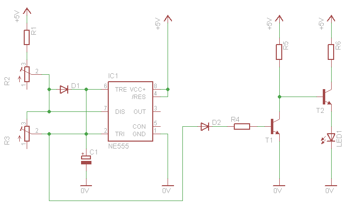
The Circuit
I do like microcontrollers, but i prefer analog electronics whenever possible. I quickly searched around the internet to get ideas of analog breathing LED circuits, but i did not found something that i liked. So i designed my own pulsing LED circuit with a 555 timer:
The circuit on a breadboard for test
Generally, when we talk about ramps and delays in analog electronics, we talk about the charging and discharging time of a capacitor. So, i began designing the circuit around a big capacitor. The 555 chip is connected as an astable multivibrator. If you put the oscilloscope probe across the capacitor, this is what you will get (click to enlarge):
For me, this is a very cool breathing ramp! So i get this ramp through a decoupling diode and a big resistor to the first transistor current amplifier, to amplify to a usable level without disturbing the charging/discharging process of the 555 chip. Then i further amplify the current with a second transistor amplifier, which finally drives the LED. So simple! Now look the voltage across the capacitor (yellow channel) in comparison to the voltage across the LED (blue channel):
Breath in... Breath out... But how fast? To get the most out of this circuit, i added the D1 diode. This diode allows the 555 timer to achieve duty cycles less than 50% (which normally doesn't). Moreover, i added 2 different potentiometers. The R2 potentiometer adjusts the fade-in time, and the R3 potentiometer the fade-out time. So, you may adjust the circuit to act as a breathing LED, or as a flash-in fade-out LED, or as a fade-in flash-out LED.
Finally, something about the LED voltage and current. Different LEDs require different forward voltages and draws different current. You may need to change the value of R5 to change the voltage across the LED and R6 to change the current.
Awesome! Thank you so much, I added this great LED feature to my project, built last night, really cool effect!
At 17 March 2015, 5:22:53 user Dan wrote: [reply @ Dan]
Hi,
I just want to hook up multiple leds using to this 5v powered circuit
I am looking to hook up 5, 10 and 20 leds
How do i calculate ?
What should i do?
Thanks
At 14 July 2014, 10:41:28 user BoB wrote: [reply @ BoB]
Good Morning, Thanks for the replay :)
I made my first attempt at the circuit this weekend however the LED will only complete 1 lighting cycle. After that it stays dark. I've checked my connections 3 times and can't see anything amiss. By chance, do you have any suggestions on where I went wrong?
Thx
BoB
At 8 July 2014, 11:19:56 user BoB wrote: [reply @ BoB]
Looking at the parts I have on hand, would I have anything to worry about if I was to use a 680uF Cap (instead of the 470), and if there would be a problem is it something that can be easily remedied? (my local shop can be a bit of a pain to get to so I'd rather not go there just to pick up a couple of 470uF)
(This will be used in a computer case mod)
Much Thanks for any help you can provide, I'm a complete amateur.
BoB
At 25 April 2014, 20:29:39 user Kert wrote: [reply @ Kert]
I tried this circuit diagram and I only get a steady-lit LED. It does not pulse/breath :(
@Erwin pin 3 flashing means that the 555 is correct. So your problem is somewhere on the amplifier. Get yourself a 470K potentiometer. Replace R4 with this potentiometer and a 10K resistor in series. See if you get if fading somewhere within this range.
At 18 March 2014, 20:52:51 user Erwin wrote: [reply @ Erwin]
sorry but my english is not so good ....I do not know what I'm doing wrong :-(...but when I make the power supply.... the LED goes once on and off....and then she stays out ....However, when I connect a led on output 3 flashes adjustable with p1 and p2 .....but do not want flashes...i want fading ..pleas can you help me to find out what I'm doing wrong ....thanks in advance...Greetz Erwin
At 21 February 2014, 6:16:43 user Foxter wrote: [reply @ Foxter]
I found this :
http://www.projectik.eu/index.php/elektrotechnika/microprocesory/item/227-dychajuca-led
That's exactly what I ended up doing, Thank you! I also put a 10k resistor in parallel with r3 to balance the fall time, and a toggle to switch between 470u and 100u for more range. This thing is wacky fun . Thanks, G!
@ampcamp I'd rather use a linear regulator, say 7805 or something similar. Other than that you need to be very careful of choosing part values.
At 24 September 2013, 18:50:08 user ampcamp wrote: [reply @ ampcamp]
G, this is a great little circuit. I've got it running on my bench, and everything is as you described. Two questions. I've got it running off of a usb cable at the moment, and it works exactly correct. I would like the option of running this off of a 9v battery. Would you use a zener, a voltage divider, ceramic resistor, what? I plan to use this as a LFO with a photo resistor to control an audio circuit. How to get it to go slower and more symmetrically "even" ?
At 19 September 2013, 20:39:30 user train wrote: [reply @ train]
I build the circuit with normal LED but doesn´t work. I don´t know why :( I'm cluelessall.
@train Too much power dissipation on the transistor. It will fry!
At 18 September 2013, 10:54:37 user train wrote: [reply @ train]
Can i use LED cree diode with rate Voltage: 3.2~3.6 V / 1.5A(MAX.)
Thanks
At 18 September 2013, 9:39:35 user Shane wrote: [reply @ Shane]
Hi, I was hoping to build one of these to power lots of different LEDS. I want to have 10 12v outputs running in parallel. Attached to each of these 12v outputs will be different number of leds, one may have 6 2V leds in series or another may have 4 2V leds and a resistor. I would like to be able to adjust the fade time as well. How could I adapt this circuit to provide that much power (there will probably be somewhere around 30 leds powered.) Thanks for you help.
@Fung Scope the base of the transistor and you will definitely find the answer. I bet that the transistor you use has greater hfe (typical problem for transistors even of the same batch). So it was driven to saturation with smaller current...
At 20 August 2013, 8:17:51 user Fung wrote: [reply @ Fung]
@Giorgos Lazaridis I tried to use a smaller value of R4, it still did not work, however when I change it to a larger value such as 680k, it worked well.
@Fung Then it sounds as current problem from T1. Maybe change R4 with a smaller one, or check it T1 has enough hfe...
At 2 August 2013, 7:04:07 user Fung wrote: [reply @ Fung]
@Giorgos Lazaridis I use a new BC547 transistor for T2, and I keep monitoring the change of voltage at the emitter pin of it, it is observed that the voltage was 4.8V at first 500 milliseconds, and then it keeps 0V constantly so that the LED does not light. Nowhere I use another transistor such as BC548, the same observation is still obtained.
At 28 July 2013, 16:38:01 user Fung wrote: [reply @ Fung]
By checking the voltage at the emitter pin of T2, the voltage was always below 1V so that the LED does not "breath", however if I connect the LED and R6 at the emitter of T1 (T2 become no use), while the collector pin of T1 connects to 5V, it works, why?
I have also breadboarded this but cant seem to get it to work. The LED is just on. Is there a revised schematic anywhere?
Cheers
At 11 July 2013, 16:09:34 user NTSS wrote: [reply @ NTSS]
Can anybody tell me if schematic I've made is correct? The schematic is 100% based on circuit from this topis about breathing led. I arranged this on my breadboard and effect I received is brething out led but without breathing in (no loop). Please help me ;)
At 19 June 2013, 21:56:08 user Dave wrote: [reply @ Dave]
@Sal Cortez
I misread your post before my previous reply.
Check out talkingelectronics (dot) com
They have LOTS of LED circuits and should have something to help you design what you want.
At 19 June 2013, 21:46:17 user Dave wrote: [reply @ Dave]
@Sal Cortez
See my previous post. If you wanted to alternately fade two separate LEDs, with my design, you could simply use an NPN transistor for one and a PNP for the other. Since the OUTPUT pin #3 alternates between source and sink ("Pushes" and "Sucks" current), when it pushes/sources it will activate the NPN. When it sinks/sucks current, it will activate the PNP. Use separate diodes in direction of current and a separate RC network (resistor with Capacitor to ground) between each diode and transistor to better control the direction of current and charge/discharge of the capacitors for timing the "fading" or "breathing".
.....I wish there was a way for me to post schematics or videos in the comments here.
Good Luck!
At 19 June 2013, 21:39:51 user Dave wrote: [reply @ Dave]
Nice, creative circuit! Thanks for sharing!
I'm not sure if it's much simpler or not, but I have created similar results (also fully adjustable) using only one transistor. (I can upload/email you a schematic if you'd like.)
Basically, just set up a basic astable multivibrator with the 555. Then, off the OUTPUT, pin 3, put a resistor (10k?) then a capacitor to ground (100-1000uF polarized) then an NPN transistor with resistor and LED.
Since pin 3 alternates between sourcing and sinking, I eventually added a diode between pin 3 and 10K resistor to prevent the 555 from draining the capacitor & slow down the "fade off" of the LED.
Theory -
The RC network between pin 3 and transistor slowly turns on and off the transistor as the capacitor charges and discharges. This timing can usually be easily calculated by simple multiplying the resistor and Capacitor values. (Ohms x Farads = Seconds, I believe.)
In simulations, my meter readings looked very similar to your triangle wave. After some adjustment, I was able to get it to look (almost) like a sine wave --- which is what Apple's goal was with their status light. (Google Apple's patent for "Breathing LED Status Light for reference.)
I've created a PCB using this design with a decade-counter IC to slowly turn off and on a series of 6 LEDs one by one. It looks REALLY cool. I'll try to post a video somewhere and link it along with EAGLE files, etc.
Thank you for posting your circuit for the 555 Pulsing LED Circuit
I would like to use your circuit set at as a fade-in flash-out setting.
My question to you is there a way when your 555 circut ramps up to triger a second LED to Flash or triger a second 555 circuit to cause a second LED to flash
hy guys i had made same circuit but the LED high for a moment then it become off , when i give it supply again then it not work, after 3 second it removing supply.. giving supply again it do the same thing high for a moment and then off ,,,, kindly guide me plx...
@Kevin I would use 5,9 or 12v. then use appropriate resistor @R6 for the Led. this is a handy online Calculator for this;
http://led.linear1.org/1led.wiz
I would get a bread board to test it out with. R5 seems to change drastically w/ different LED's and voltages.( check NOV 10 for Sam Fischer's post) I used a 1k potentiometer to figure out the exact R value for R5. when you have it working put a meter on the "Pot" to see what you came up with. then replace the pot w/ that R resistor to make sure you have it right. Battery's: Radio shack has a lot of small ones w/ different V.
At 15 November 2012, 19:08:12 user Kevin wrote: [reply @ Kevin]
Hello!
I'm looking to make this circuit (or something similar) for my family for Xmas (am going to have a custom PCB made for them), but this will be my first "circuit" that I create that doesn't involve arduino (I'm new in general to electronics).
Anyway, my question is, is this circuit something that could be powered by a battery of some sort? Ideally I was thinking of using a watch cell, but somebody asked earlier I believe about using a 3V battery and the word is that it's not powerful enough?
My Goal is to make a nice, tight looking pcb with an on/off switch and a "breathing" blue LED.
@DragonWire well, this is not exactly an "elegant" way to solve your issue, but if it works then i'm happy! Enjoy!
Nevertheless, you can still work on the previous circuit, add or remove an inverting transistor before your fet, and get the same result with a more professional way. I know that polarizing a fet is a headache (to work on the linear area of the FET)... but... you know... It is the sauce on the hotdog...
@Giorgos Lazaridis Whoo hoo!!!.. found your post "LED Fade-In Fade-Out Dimmer" I just built a test on the V rail to power a single bulb. with THIS curcuit running the V- rail through a N-fet. Works great. I'll use the (BD243 power transistor)running about 25 20ma 5mm greens on the V rail feeding the Leds. The (470uf C 35v)I have was a Really a slow fade up. I tried a (16v 100uf)I had, a little faster than I want. I'm going to get a 200uf to try out also. I pan on using the "LED Fade-In Fade-Out Dimmer" for another feature of the sculpture.
@Giorgos Lazaridis Uggg well I tried #2 and #3 suggestion. neither seems to work for me. even tried switching the new PNP-T around in case I had it in backwards. Bulb comes on full at power up no matter what I do. And the additions had it not fading at all, even after playing w/ resistor values.
I didn't try #1 ( "with gain=1 between T1 and T2") total noob not sure what than means or what to connect to what.In theory these SHOULD work. I read about what a PNP does. my test board is running to a Led, and through a fet to a bulb. having no success with either bulb. Am planing on having an Arduino to time control lots of kit controllers. for other things going on on my sculpture. So maybe a pmw output to a fet then possibly a bridge rectifier to slow start the V if a rectifier will work that way. but I do have your curcuit working great, other than it comes on full blast when I switch it on.
@dragonwire During startup, the capacitor C1 i discharged, T1 inverts this signal so at startup it is fully HIGH, and so does the T2 which is emitter follower. You need to do one of the followings:
1. add another inverting transistor with gain=1 between T1 and T2
2. add another inverting transistor after T2
3. Replace T1 or T2 with a PNP
one of the above will invert the output signal, so it will start from LOW when turned off.
@Giorgos Lazaridis Yes Fet is after T w/ a pot between as I said. When I remove T2 I just get a steady on. What I looking for is something I can put on the V That heads directly to the Lights that I can separate from your fading circuit that will gradually go from 0-5 volts. something like a soft start circuit. Or a way to have your curcuit start at Low when power in turned on so it Fades slowly up first. I have spent a while online looking for this, all I can find is Soft start motor controllers, or converters. Maybe there is some IC out there that has a PMW function ? use a Fet and rectifier. But I'm so Jazzed I got your circuit to work at all. It took a lot of trial and error to get it working right. Right now I have 2 4.7k R in place of your Pots. I tried it with several variations all working well now.
@Giorgos Lazaridis Love this thank you so much. I've worked this out to use w/ a N channel MosFet. I have a 10k pot after (T2)about 5k seems to work best, then to Fet. To power several Leds that are pre-wired w/ a R and have V directly to them. the circuit is controlling V- I already had the Led's in place. The R5 worked out to be 390. though I am going to make 16 of these and plan on having a 1k pot for R5 for fine tuning each. And in place of your 2 Pot's varying R from 4.7 to 15K so they all fade in and out at different times. My only problem now is it starts at full power. Do you have any idea's how to have the Common V slow start, so when power is turned on the system fades slowly on, then power off fades out. I'd need to control this from the V rail I imagine, but maybe not.I have 24 green Leds total on that rail @20ma so it's less than 1/2 amp @ 5v. It's for the body of a Dragon sculpture. I do have the fading set so they don't go fully off either. Very cool effect.
Thank you. Have been looking for a 5v circuit to do just that. Is there a way to modify this circuit to run two LED's opposite each other. ex. have a blue LED breathing in as a red LED exhales
Dear Sir,
How can I make a fake alarm 1 LED with adjustable flash rate using potentiometers so that it doesn't flash fast and look so fake. I would really appreciate if you could help me with a simple circuit to diy.
Thank you.
I'm a prop maker in Los Angeles. I have no circuitry experience & a short time frame.
Would someone be willing to make a few of these adjustable pulsing circuits for me, at a reasonable cost? I need one right away for a light box sign with LED's. And I would want a few more down the road for both low voltage LED's & 110v.
Ok, i've just made a new LED breathing circuit with variable output. It operates at 12 volts and can control any LED that operates from 12V and bellow (tested also with 21W 12V incandescence lamp and worked).
@vimal R6 has only to do with your LEDs, so you need to change R6 only if you change LEDs. As for the transistor, since it is am emitter follower, a darlington will work better than a simple transistor.
At 19 December 2011, 17:52:43 user vimal wrote: [reply @ vimal]
when changing the npn transistor T2 to a higher one,should i change the resistor r6?
will this darlington pairs work?
tip142
At 15 December 2011, 2:42:45 user CN. wrote: [reply @ CN.]
good idea for x-mas light.. thank you :)
At 8 December 2011, 9:08:07 user binoy wrote: [reply @ binoy]
sir. what all changes i have to make in this circuit for using a 9v supply instead 5v ?
As an add-on to my last post, I forgot to thank the author Kammenos. This schematic helped me figure out what to put where. Initially it did not work, but I was also using different transistors so I did not expect it to work on the first try.
I used 2x 3904 NPN transistors (instead of a bc337 & 2n2222)
'C1' I used 2 470 uF caps in parallel
'R5' I used a 420 ohm resistor
'R6' I used a 100 ohm resistor (but this will change depending on the current requirements of the LED and the Vsat of the transistor)
With this I get a nice smooth fade around 3 seconds off to off (longer with higher 'C1' value) and a quick blink if I adjust the 10k pots the other way.
FOR EVERYONE WITH QUICK ON/OFF OR CONSTANT-ON LED...
If constant on....increase R5 (POTs are good for testing)
If quick on then off forever....decrease R5
For longer fades and more control with the 10K POTs....increase C1
ABOVE ALL triple check wiring...I have yet to wire a circuit with more than few parts correctly the first time.
At 25 October 2011, 23:49:37 user toby wrote: [reply @ toby]
I am trying to make a similar circuit but I cannot get it to work. the led just stays on and does not fade on and off. The only thing I can think of is I am using 1/8 watt resistors and not 1/4 watt. Here is the link to what I want to build http://www.instructables.com/id/ThrobbingFading-LED-with-555-Timer/ . Also does the voltage of the capacitor matter? Thank you.
At 9 October 2011, 20:54:21 user Roger wrote: [reply @ Roger]
YUP that Yenka simulation software is amazing as usual! I built the original circuit with these modifications and it works perfectly!! R2= 100k , R3= 100K, C1= 100uf, R4=110K, R5=3K. The only reason I changed the pots was because I didnt have spare 10K pots so the original 10k values with the 470uf cap should work the same. Its resistor R4 & R5 that made the difference for me.
At 9 October 2011, 20:19:23 user Roger wrote: [reply @ Roger]
I was having problems with this circuit so I decided to draw it out in the Yenka simulation software. Same issues until I starting varying the resistor values R4 & R5. Right now I have R4=120K & R5= 3K its working great now! Seems to be finiky matches these values to your LED then once this is working using the pots to vary the dimming seem to work as seen in the video, at least through the software. I'll try it on the breadboard soon.
@RCC bc337 has much larger hfe than 2n2222, and 2n2222 has metal package which can take heat sink and manage almost double power dissipation than bc337
At 4 October 2011, 13:35:54 user RCC wrote: [reply @ RCC]
Why are T1 and T2 different? The specs between BC337 and 2N2222 are more similar than they are different and these 2 often can be interchanged.
@Jayson i'm working hard and intensive to get it right and get it fast. I do not want to be "yet another transistor theory". I get knowledge from 3 different books and i have email conversation with a transistor manufacturer to make something nice. It will take me some more time, because this weekend i could not work, and this week may be hard as well.
Have you finished re-writing your transistor theory? Before I continue my attempt to have this circuit work for 12VDC I would like to read your additional theory information.
Thanks again.
Jayson
@Jayson something like that, but not exactly. The second transistor will not work exactly as an amplifier. The output of T1 may be around 5 and 9 volts (these values are not be real, just an example). The intermediate transistor has to change these numbers to the min and max voltage that your LEDs need to operate (for min and max brightness). That could be 5 to 12 volts or something different. An oscilloscope would be a great help for you at that point.
I have just began (today) re-writing the transistor theory that i already have in my site. The new theory will have more than 4 pages and it will explain in details how you can calculate and design the most commonly used transistor amplifiers. One of the chapters is the type of amplifier that you need here. Maybe this will help.
At 28 September 2011, 14:35:29 user Jayson wrote: [reply @ Jayson]
Kammenos:
Are you suggesting to build a Darlington pair with T1 C to T3 B, T3 E to T2 B and T3 C + R to Source? If so I will try tonight. Obviously this problem would be easier to handle with a PIC but what fun would that be :-).
@Jayson the easiest solution is to add a 3rd transistor between t1 and t2. T2 works as a voltage follower, which means that it will output the same voltage as it receives at its base, it cannot scale the voltage. T1 operates as an amplifier, the output voltage depends on the current of the base and R5. You could add some potentiometers to try and scale the t1 output, but it is kinda difficult. I suggest you add a transistor in between to scale the voltages. I cannot suggest you which resistors to use because you have to find yourself.
At 28 September 2011, 3:21:40 user Jayson wrote: [reply @ Jayson]
Kammenos:
I'm unfamiliar with transistor polarization. If you have a extra moment would you explain it?
I had no luck with add a resistor/pot(100k) to the right side of R4. In fact when connected to base of T1 it disabled the Leds.
The voltage divider did work to help bring up the brightness a bit but did nothing for the min light level.
I experimented more with changing the values of R1, R4 and R6 with no luck. Would I have better luck using a power transistor, a 3rd transistor or possibly a op-amp?
Again thanks for your time and help with this. I hope to have this working in the near future.
@Jayson the whole problem is at the polarization of the first transistor. It is calculated for 5V. The 555 has nothing to do wit the LEDs, and nothing can change on the 555 side to work better. If the MAX brightness is ok but the MIN is not, then you have to pull the base of the transistor to positive a little bit.
So, next step is to add a resistor from the right side of R4 to +12V. The resistor must be very large, larger than 47K. To save time, i recommend you use a potentiometer with a resistor. The pot is 100K and the resistor 33K (together make 133K). Connect the left pin of the potentiometer to the 12V. then connect one side of the resistor to the mid connector of the pot, and the other side goes to the right side of R4 (at the base of T1). Rotate the potentiometer to both sides and tell me what happens.
If this does not work, then you have to polarize the transistor with a voltage divider, like Fabio did (previous comments) and worked.
At 27 September 2011, 15:48:53 user Fabio wrote: [reply @ Fabio]
i've resolved! since it is a problem with T1 polarization i've made a really simple voltage divider adding a 33k resistor from T1 base to ground. now it work pretty well. I hope it will be usefull for other people! enjoy this circuit!
Fabio
At 27 September 2011, 15:23:43 user Jayson wrote: [reply @ Jayson]
@Kammenos
Thanks for the quick response. To clarify my technical issue at 12VDC the led's are bright. At 12VDC the problem is the Led's do not fade to off or nearly off. They simply dim and then fade to bright. I suppose my voltage is not getting low enough to turn them off. To be honest Im a little stuck on what to do next. Is it possible the duty cycle of IC 555 is too fast for 12VDC?
Thanks again.
Jayson
At 27 September 2011, 15:18:28 user Fabio wrote: [reply @ Fabio]
3mm blue led i think is 1.5v 20ma but not sure of this. can be the 100k's resistor that doesn't let flow the least amount of current?
@Fabio then i suppose that t1 is the problem. what led you use?
At 27 September 2011, 15:01:28 user Fabio wrote: [reply @ Fabio]
although voltages on capacitor is ok, on the base of T1 (bc337) i found 0.7 voltage stable, isn't it wrong?
At 27 September 2011, 14:55:12 user Fabio wrote: [reply @ Fabio]
i've checked but diode is right. on capacitor i have voltages from 1.7 to 3.4 volt which is right i think, but led remains dark. can be a problem with T1? i have tried bc547
@Jayson To tell you the truth, this is not going to be very easy. I have not test the circuit with 12 volts, but i know that you will need to add an additional transistor between T1 and T2 to scale the voltage to the desired level. This circuit works fine for 5V because there is no much scaling to do for an LED, as the voltage across the capacitor is pulsing between 2 and 3.5 volts, perfect for the LED.
After the complaints regarding this circuit, i remade it following the posted schematic. At first, the same error happened to me! So, i watched the video to find a close shot of the circuit. it is here:
http://www.youtube.com/watch?v=f5BSn9xLXhk&feature=player_detailpage#t=14s
So, i made the changes according to what i see from the video and worked. Then, i redraw the schematic and guess what! It was exactly the same as the one i have already post! Most probably i made the same mistake that most do: Put the diode D1 wrong! Make sure that the strip of the diode (cathode) is facing pin #6 of the 555. If the strip faces pin#7 then he LED will flash instantly on and then fade out.
Please check your connections. If necessary use the forum to post images (close and clear) from your breadboards to see. If there is indeed a mistake in the schematic, please let me know to fix it.
At 27 September 2011, 13:49:11 user Fabio wrote: [reply @ Fabio]
i've completely reassembled the entire circuit but problem still remain. i think there is a mistake in schematic, if anyone can fix it please advice we others.
At 27 September 2011, 13:26:23 user Ron T wrote: [reply @ Ron T]
Hi all,
I just tried to register on to the forum so I can post some pictures I took of my setup on this project but I did not get my acctivation email,tried resending a couple of times to no avail.My email adress is current and working fine.Any thoughts on how to fix this?
Thanks,
Ron T.
At 27 September 2011, 12:43:20 user Jayson wrote: [reply @ Jayson]
First I would like to thank you for sharing your knowledge with the rest of us. Like the others I have built the circuit and are experiencing some technical difficulties with the LED of choice. I am using two segments of a strip led. They are 12 VDC, 300mA and have their own resistor per 3 led light segments.
The problem that I face is that I can get the breathing to work at 9VDC but I had to change C1 to 100uF, Both POT are 100K , R5 2.2K, T1 is MPS2222A and the IC is NE555P. With these values and at 9VDC it doesnt dim completely and doesnt get bright enough. When another 3 VDC is added to the circuit the breathing effect is barely noticeable. I have tried different combinations of resistors and capacitors and have no luck.
I realize that my pots could be to large but it should only effect the fading times and not the brightness. Correct?
Any ideas on what I should do to have the circuit work as yours but only at 12VDC?
Thanks again
Jayson
At 27 September 2011, 8:43:40 user Fabio wrote: [reply @ Fabio]
hi guys! i've just realized this circuit but have a small problem like others, my led suddenly get on and slowly dimmer off but for only one time? can be a mistake with the schematic posted? all my components are new and i've realized it on pcb.
Fabio from Italy
At 27 September 2011, 0:02:34 user Ron T wrote: [reply @ Ron T]
I've tried 3 different leds as follows,
1.85 V @ 20 mA
@Ron T what LEDs have you used? What is the forward voltage and current? Are they high brightness or simple LEDs? Post some detailed images of the breadboard in the forum for more.
At 26 September 2011, 9:58:22 user Ron T wrote: [reply @ Ron T]
I built your circuit last night and can't get it to work.I have the same problem as Fung had just one flash.If I disconnect and connect the power multiple times in a row the led slowly gets dimmer and dimmer and then finnaly stops lighting even with the power still connected.All the components are new and I followed the circuit diagram and put the components on the breadboard as shown in the pictures.Any help you can give me would be great.
Thankyou,
Ron T.
I want to use this for a 12V led lamp which is build to replace a 12V halogen lamp. The led is 12V and 1W.
There is elektronics in the led which makes it run on normal 12V halogen transformer and also dimmable.
How can I change this schematic to power this led bulb?
Do I for example need to add a fet or something?
I need all to work on 12V dc power.
Thanks for your help.
(I also need a small motion sensor (the one with a spring inside which act as a switch) to power this on and a timer to power it off after for example 1 minute without motion. Could I use the same 555 for this, with an separate C and R?)
@Fung make some good photos and upload them in the forum (http://pcbheaven.com/forum/) so that we can help you
At 9 August 2011, 4:25:13 user Fung wrote: [reply @ Fung]
I tested this circuit on breadboard referring to the circuit diagram above, it is found that the LED has been flashed once and no breathing effect is observed, I have checked the routes are correct, where is the problem and why?
@Fung when C1 decreases, then you must increase R1 R2 R3, but the effect will not be the same. You need to make several tests to achieve a nice breathing effect.
There is no allowed range for C1. If you decrease the capacitor to 100uF for example, then you have a flashing rate x4 which is very fast. It all depends on what you ask for. You may then consider using 100K potentiometers or even 500K.
At 8 August 2011, 13:26:09 user Fung wrote: [reply @ Fung]
What is the allowed range of the capacitance of C1?
If small capacitance of C1 is used, what modifications should be taken on R1-3?
@Fung yes the output is a typical square wave but i do not use it.
At 3 August 2011, 3:10:09 user Fung wrote: [reply @ Fung]
What a good circuit, however I am going to know about the output of the timer because it is not used in this circuit. What is the expected output pattern at the output of the timer? Just the normal square waves?

 Home
Home
 Projects
 Experiments
 Circuits
 Theory
 BLOG
BLOG
 PIC Tutorials
 Time for Science


 Contact
 Forum
Forum
 RSS
RSS


 Reddit this

