
|
 Home Home
 Projects Projects
 Experiments Experiments
 Circuits Circuits
 Theory Theory
 BLOG BLOG
 PIC Tutorials PIC Tutorials
 Time for Science Time for Science
|
| ||
|
4 July 2009 Author: Giorgos Lazaridis Ambient Light Level Equalizer The circuit onoperation (LEDs cannot be on because the flash turns them off instantly). The left potentiometer will adjust the highest level of operation, and the right will adjust the highest LED brightness. Ambient light level equalizer is a way to keep the light luminosity at a desired steady level. What this equalizer does, is reading the ambient light level, and according to it, it will increase or decrease the luminosity of light sources such as LEDs. The level is controlled with PWM pulses. There are several applications for such a circuit. It could for example control the light level in a greenhouse, keep your keyboard always steady illuminated, increase or decrease the intense of 7-segments or LCD baklits to have a better reading when dark or light and much more. look at the following video demonstrating this circuit in operation: The circuit We are going to use the voltage controlled PWM generator described in previous article and all details and theory of operation can be found in this relative page. We will then make a circuit that will create a DC level signal according to the light luminosity taken from an LDR. this DC signal will be driven to the comparator. According to the light falling on the LDR, there will be PWM pulses that will change it's duty cycle. A mosfet will drive the LEDs and dim them accordingly. An LDR is a variable resistor that changes it's resistance according to light level. The more the light on the surface of the LDR, the less it's resistance. As part of a voltage divider, this will result into voltage changes. We shall polarize the base of an NPN transistor with such a voltage divider, and from it, we will get the desired signal. This circuit would look like the following: 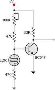
The above circuit will generate a voltage output from zero to Vcc (5V) according to the LDR's resistance. The 100K potentiometer will set the lowest point where the circuit will start operating. When this circuit is interfaced to the voltage controlled PWM generator, the 100 K resistor will actually control the highest light level that the LEDs will be still turned on. While light falls below this level, the LEDs will gradually become lighter and lighter. We could interface the above circuits directly to each other with no problem at all. But i had a better idea. Suppose that at maximum darkness (minimum light), someone did not want to have the LEDs at full brightness. I added another potentiometer between those two, and this would control the maximum brightness of the LEDs. This potentiometer is a 5K performing a voltage divider between the two circuit. Therefore the driven voltage from the transistor to the comparator will depend on this potentiometer. Putting it all together, this is how the final circuit looks like: 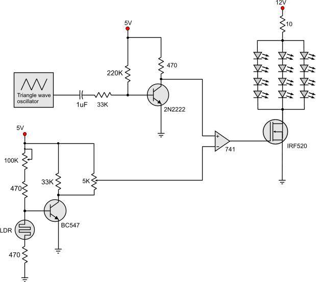
Adjusting the circuit It's time for some adjustments. First, the 5K potentiometer (if you have added) should be somewhere in the middle. It does not really matter if it is not exactly there, just avoid the edges. Then, turn your lights on. Get the highest ambient light that you wish your LEDs to be still turned on, dimming like dead candle. At that point, turn the 100K potentiometer so that the LEDs are right at the off-edge. Afterwards, turn your lights off. The 5K potentiometer will control the full brightness of those LEDs. Do this and you are ready to go! Relative pages Comments
|
|
 Contact Contact
 Forum
Projects
Experiments
Circuits
Theory
BLOG
PIC Tutorials
Time for Science Forum
Projects
Experiments
Circuits
Theory
BLOG
PIC Tutorials
Time for Science
 RSS RSS
Site design: Giorgos Lazaridis © Copyright 2008 Please read the Terms of services and the Privacy policy |


 Reddit this

