The PWM fan controllers have many advantages against other rpm fan controllers. Yet, they tend to be difficult in construction when high frequency is required. The PWM controllers usually generate acoustic noises, when the PWM frequency is within the acoustic spectrum (20Hz to 20KHz). A high frequency PWM controller usually operates above the 20KHz, thus the human ear cannot hear this sound. Moreover, PWM controllers can achieve very stable and low speeds without the possibility of a fan stall.
The circuit that i will present to you has all the advantages of the high frequency PWM controllers, but it uses only a 555 timer to generate the pulses. Although the frequency is not very stable (come on it is just a 555 for crying out loud), it will never fall bellow 21KHz thus you will not hear a thing
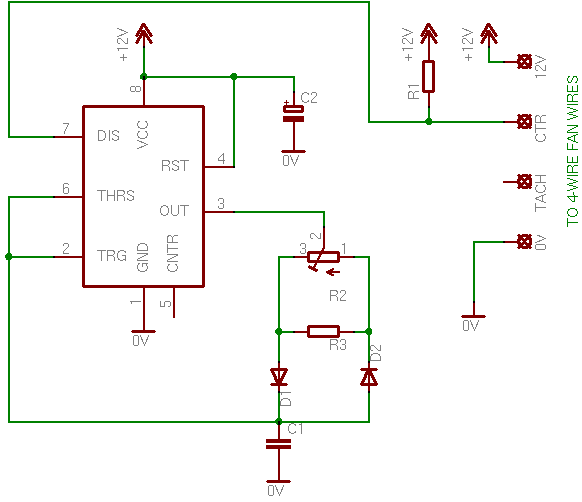
The circuit
The circuit is very easy to follow. The output (pin 3) of the 555 timer will control the charging and the discharging of the capacitor. This is the only point that needs of your attention. Usually the capacitor is charged through a resistor directly connected to the power supply, and discharged through pin 7 (discharging capacitor). Now the capacitor is charged from the output of the 555 when it is HIGH, and discharge the same way when the output is LOW. The frequency is calculated from the capacitor itself ( C1 ) as well as from the total resistance of the potentiometer parallel to R3.
Here is the circuit:
The PWM pulses
The duty cycle is changed according to the position of the potentiometer. For the complete period calculation of a pulse, the total resistance of the potentiometer (in parallel to R3 of course) is calculated. But, during the charging of the capacitor, the current goes only through D1, and during discharging, the current goes only through D2. This, according to the position of the potentiometer, the charge period and the discharge period will change, but the complete period of the pulse will always be the charge period plus the discharge period! That is the whole idea of the PWM generation.
Unlike a normal 555 astable multivibrator circuit, the output is taken from pin 7. If you see the internal diagram of a 555 timer, you will see that pin 7 is connected to the discharging capacitor. But the discharging is taken over by the output of the 555, as described above. Thus this pin is free to be used. A resistor is connected to this pin and the it turns the internal transistor into a switching transistor (inverting amplifier). As a result, during the discharging time, pin 7 is logic LOW, while during the charging time pin 7 is logic HIGH. This is driven directly to the control wire of the 4-wire fan. No driving transistor is needed, as we use the internal 555 transistor for this. The rest is taken over by the fan controller itself, as the 4-wire fan carries internally the switching FET (see page "How PC Fans work").
The 4-wire fans have a very clear RPM feedback even if they are driven with PWM pulses
17 Hz (510 rpm) is the minimum rpm predefined by the manufacturer.
64 Hz (1920 rpm) is the maximum RPM
Bill Of Materials (First circuit)
Resistors
R1
Resistor 1 KOhm 1/4 Watt 5% Carbon Film
R2
1 KOhm potentiometer
R3
Resistor 4.7 KOhm 1/4 Watt 5% Carbon Film
Capacitors
C1
0.1 uF ceramic capacitor
C2
1 uF 16 Volts electrolytic capacitor
Integrated Circuits
IC1
555 Timer
Diodes
D1
1N4148 Switching Diode
D2
1N4148 Switching Diode
What about the 3-wire and the 2-wire fans?
A 3-wire fan connected to the circuit on a breadboard for test
No problem... almost... You see, 4-wire fans have internally a switching FET, something that 3-wire and 2-wire fans lack of (see page "How PC Fans work"). Thus, we need to add this FET externally. The circuit is the following:
You may notice that i have add another resistor to the circuit, the R4. The R4 will prevent the fan from running at very low speeds with the possibility to stall. Actually, the circuit will now generate a minimum duty cycle of around 40%. You may change this resistor to get lower or higher initial speeds.
You need to have in mind also, that, in case you use a 3-wire fan, the feedback from the third wire cannot be used. Instead of the revolution pulses, the third wire will return the PWM pulses. If you want badly to have rpm feedback from a 3-wire fan, you should consider using other circuits:
I want to make sure, this NE555 circuit is running PWM at 2.4 HZ frequency for sure? (not for example 2.4kHz?).
Im trying to filter square wave PWM output to "DC voltage" output using RC filter and im having problems picking R and C values. Most of them work fine on kHz frequencies but cant seem to find proper combination for low frequency such 2.4Hz
At 25 June 2015, 14:07:53 user Phil wrote: [reply @ Phil]
The LTspiceIV file is here.
https://www.dropbox.com/s/p0y638zwgw8jayc/22mhz-PHIL.asc?dl=0
Replace R4 with a 10k thermistor and put your fans in series at the TOMOS link. The fans will run at a frequency of about 22Mhz, the duty cycle will change according to temperature. When at 20 degrees the duty cycle will be circa 20% and at 50 degrees the fan will be fully on. The application was for a internal PC case fan but you can play around with the voltage divider R4/R3 to adjust the duty cycle according to temperature.
I got rid of the POT and use fixed resistors instead to set the frequency high enough that you cant hear the fan noise. At each pulse the fans get a full 12v so its virtually impossible for them to stall.
I am working on a modification of this circuit to add some LEDs for status and a switch to clear dust.
@Giorgos Lazaridis and @phil
In the case of the 2-or-3-wire circuit, is there a problem with having the frequency and duty cycle linked? What modifications to the circuit would be necessary to decouple these and avoid the squeaking? Would there be a benefit to being able to change both independently? How would that be implemented?
Application: I am linking a set of fans into one long strip to ventilate a large-volume but narrow space. Manual control of speed (and dB) is important. Temperature dependent automation is actually undesirable.
Thanks much!
At 24 April 2015, 20:12:43 user Fan wrote: [reply @ Fan]
@Giorgos Lazaridis @phil could we see the version with temperature sensor in the loop instead of our own eye-brain-hand ;)
Thank you
At 23 February 2015, 20:59:59 user Juan wrote: [reply @ Juan]
Thanks for sharing your work. Really nice design and videos.
whats the maximun current that can be handled by the 3 wire fan circuit?
IRF520 says maximun current is 9.2amp, but im not sure if thats the top limit or there is a lower one.
Hi there guys, ive just complete the first circuit to controll a 4 wire fan on a breadboard but had no sucsess. im not sure weather i have messed up whilst connecting the circuit up or if it will not work because i am running the circuit on a 5v power supply which i thought i needed to do because the control has a 5.25v max rating.
does anyone have an example of a working circuit on a breadboard that you could post??
@phil Yeah we definitely want. i will add it to the page
At 1 November 2014, 10:22:02 user phil wrote: [reply @ phil]
The circuit is a an excellent starting point for developing a 12v PWM fan controller.
There are a couple of issues though. One is that the way the 555 is connected frequency and load are not decoupled so when you change the value of the POT you will change both the freq and the duty cycle at the same time. In practice this will mean you will hear some squeaks as you turn the POT as the frequency changes.
If you want to use this circuit to vary fan speed based on temperature then one way you can do this is by just adding a comparator. Use the triangle waves generated at the THRES pin and pass them through the inverting input of a comparator. Your reference voltage on the comparator should be connected to a voltage divider (between say a 10k NTC thermistor and a 12k resistor). The output of the comparator could then drive the MOSFET, higher temperature would generate PWM waves with a duty cycle increasingly closer to 100% on.
If anyone wants I can post the schematic i used for doing this.
At 19 September 2014, 3:53:19 user girish wrote: [reply @ girish]
Sir
where does CNTR pin 5 from IC is connected
what if not connected
I am using a 2 wire motor
and want to turn it in both direction but very slowly
do you have some ideas of doing the same and how to connect it
it will be used to work as a lift
thanks
girish
At 9 September 2014, 1:33:28 user Chris wrote: [reply @ Chris]
The wiring diagram for 4 pin fans is incorrect - the control pin and ground pin are swapped. As well, the voltage supplied for the PWM signal is incorrect - it should be 5V. See http://formfactors.org/developer/specs/4_Wire_PWM_Spec.pdf
As far as I can tell, the given circuit actually applies modulated 12V power back through the ground pin of the fan, in effect completely bypassing the fans built in PWM circuitry and directly modulating the voltage the fan motor receives, in a manner similar to the 7V fan adapters that connect the fans ground to the 5V line(in this case, being 0V net).
For use of a 555 timer to generate a proper 5V PWM signal (or a 556 for a stronger signal capable of driving multiple fans) see http://www.overclockers.com/pwm-fan-controller
@Gaute Mikkola in fact in most of the cheap 4pin fans there is just a fet and a pullup added vs. the 3pin ones. You can check that with a fan attached to 12V, control pin voltage measured with multimeter towards ground. As the PWM signal generating logic on the PC mainboard runs off 5 or 3V etc, some mainboards have an voltage limiting diode on these signal lines. As long as the pullup is big enough, only a small current flows thru these diodes which is no problem. R1 is useful to measure the output without a fan attached.
Are you sure it is alright to use a pull-up to 12V for the PWM signal?
Intel specs are mentioning "Absolute maximum Voltage level: 5.25V"
Also. The Specs does say
"The Hardware Monitor Device is required to provide an open-drain or open-collector type output for the PWM signal on pin 4..."
@andy k IRF630 is a beast, you can connect them in parallel, no problem. If it gets a little bit hot then the problem will be solved if you replace R1 with 1 480 ohms. But i do not think so. Just keep the track from the 555 to the mosfet base as small as possible and there will not be any parasitic capacitance.
Thanks, Giorgos! I decided to buy a 1k pot at RadioShack since I don't have enough understanding of the theory to know the formula of changing the potentiometer rating - they only have trimpot w/ low amperage rating but it works without any issue.
Things I'd like to share:
- I used IRF630 that I have salvaged from another circuit.
- the MOSFET stays cold for longer continuous operation.
- different fan has different tolerance of lowest duty cycle. Older fans I have tend to want at least 70% (not exact figure since I just guessed based on the position of the pot).
I have a follow up question if you don't mind, i'm planning to drive 4 fans, 12v 0.3A rating with this (i've checked their total power consumption is still well within MOSFET spec). Do I need 1 MOSFET for each fan or can I hook them up in parallel with the schematic as it is?
@andy k I hadn't analyzed the circuit back then and so I have not extracted a formula for the rc. It's not gonna be hard for one to do the a analysis, but I do not think I will do it any time soon
At 31 December 2013, 8:38:40 user andy k wrote: [reply @ andy k]
Hi Giorgos, thank you for the great collection of tutorials particularly on building PWM fan speed controller.
If you don't mind could you please explain the calculation needed for different R & C ratings if I'm using different potentiometer resistance rating (actually trimmer of 2K rated for 0.1W, will this be a show-stopper?).
My plan is to use the circuit to drive 4x 0.3A 12v 120mm computer case fans in parallel - tach is not a concern.
Thanks in advance.
@Wrrr 10-G If you use a true-rms multimeter then this is the rms indeed. Same stands if the duty cycle is 50%. You did good to reduce the capacitor, this way it increases the noise above the acoustic range.
Hi Giorgos, thanks for your circuit and excellent explanation.
I built this circuit (with mosfet) exactly, but it still gave me high pitched whines (noise) in some fans. I replaced C2 with a ceramic 100 nF, C1 with 10 nF, and increased R4 to 570 Ohm. Now I can no longer hear the noise in any fan I use, and the starting voltage measured with multimeter = 7,5 V (that should be close to the RMS, no?) so no danger of a stalling fan. Excellent!
I don't think it's necessary, but I added a 10 nF cap to couple pin5 to ground.
(according to http://www.dprg.org/tutorials/2005-11a/ )
I hope you find my feedback welcome.
@Tarneem I'm sure you can extract a formula from the components, the voltage, the capacitor and the resistors, but i have never tried to do to. i do not think it will be difficult, i just haven't done it.
Hi
I would like to ask you is there any way to know the maximum and minimum frequency (PWM) of this circuit without using oscilloscope?
I have the circuit but I need to know the frequency generated so I can easily find rpm.My fan's rpm is not written and I can't measure it. Is there any way to know the rpm of my fan?
Thanks in advance!
I am trying to wire a 12V 0.60A fan to this circuit, but cannot seem to find the right parts. I only have access to radio shack parts which begs me to ask. Could one substitute the IRF510 with an IRF520? And lastly, what adjustments to the resistors/capacitors would be needed to substitute a 10k potentiometer. Thanks!
I just tried to use the tacho signal of a 3pin Enermax fan if driven by PWM. All the fans i've tested provide the signal, but its an open collector output.
Adding a weak (100k) pullup from "tacho" to "12V" makes it possible to get a nice looking tacho signal.
@Giorgos Lazaridis: Your circuit works marvelous! I am running 5 XigmaTek fans when my motherboard absolutely refused to do so. This circuit works so well, that it even controls those pesky Dell OEM fans that only work with dell boards.
I had found another, that someone else made, but it took 2x more parts. This? It's so simple it blows my mind.
After 12 attempts to wire various circuits, I managed to not turn the 555N into smoke. Its been so long since I made a scratch circuit.
On another note, I did not add the Pull-up resistors as was mentioned in one of these comments.
Thank you for making something so simple that I didnt catch my bench on fire.
@StoneRhino normally the limit is very high. The circuit has no problem running a whole lot of fans. I do not know though what will happen to the fans and if they produce any sort of flyback reverse current
Out of curiosity, how many fans could just one of these circuits run? The reason I ask is that I've seen a few PWM circuits that cant even run 2 without some sort of amplification of the signal via a switching transistor.
@ChainFire R4 is to set a minimum speed.So if you omit R4 as well you will end up with a dead region on the potentiometer. SO use an R4. R3 you can omit it if you use a smaller R2
Hi, you said that the R3 is to reduce the resistance of R2 is that mean if I omitted the R4; reduce the R2 and R3 to simplify the circuit, the new R2 would be 500 ohm?
@jean-marc jurkiewicz R3 is to reduce the resistance of R2 because i had no smaller that time.
As for the output pin, of course you can use it instead. I usually use pin 7 though because it provides an open collector output so i can have whatever (almost) voltage i want. The problem is with the current if you want to drive current loads more than 25-30 mA
The role of R3 is not clear for me.
When I try to draw the current sourced or sinked by the "out" of the 555 to the capacitor C1 I have no current going via R3.
The classical schema for an Astable build around the 555 , where Ra and Rb defining Thigh, Tlow and using the OUT pin to control the fan pin CTR should work fine, as this pinn is (should be) the gate of a MOSFET.
@Anshul to measure current, you need to connect it in series with the load. Probably you are right. This can might not accept PWM due to the LEDs. It has 3 or 4 wires?
@Giorgos Lazaridis
i used a multimeter to measure the current and voltage, procedure as instructed in its manual(connecting in parallel across the load to measure both voltage and current).
i changed the capactor C1 to 0.05uF no improvements :(
also wanted to tell you that I ran three 80mm 12v 0.32amp on the circuit connected in parallel successfully.
I think this(link: http://www.coolermaster.in/product.php?product_id=6037) fan has some internal circuitry which is not allowing it to run on a pwm voltage somehow.
thanks anyways.
@Anshul hmmm it is a very common fan... how the leds of the fan are powered? Do they have different supply cable? Maybe they cause some sort of interference, although i doubt...
You may also use a smaller capacitor for C1 to remove the noise (acoustic spectrum PWM). You can for test connect two 0.1uF capacitors in series to have a 0.05uF capacitor, just for the test.
One question: How did you measure the maximum current? You did not put the ammeter in series with the mosfet, did you????
@Giorgos Lazaridis Im making a fan controller for my pc so the psu supplies 12v 24W on the rail, im using.
The fan having issue:
fan specs: 12v, 0.35amp, long life sleeve bearing
link: http://www.coolermaster.in/product.php?product_id=6037
The fan which ran successfully:
fan specs: 12v, 0.16amp, sleeve bearing
link:http://www.coolermaster.in/product.php?product_id=95
also, I checked the maximum output voltage and current of the circuit to the fans with a multimeter
voltage: 10.8-11v, current: 2.32amp
so the power is not a trouble at all its much more than sufficient.
so what the hell could be wrong with this circuit(2) :(
please suggest !
@Anshul what type of fan do you use? What is your power supply? What type i mean and how much volt/current can it provide.
Yes you can ground the pin 5 via a 10nF capacitor
Sir your circuit design is so far the best on the web
I had following questions regarding 3 pin fan controller:
1. Can I ground CNTR pin of IC555 with a capacitor? If yes what type and rating.
2. I'm having trouble running a 12v 4.32watt fan (it wont spin at all and produce a noise) whereas the circuit has been tested fine with a 2watt fan. can you suggest whats wrong and any solution for this problem.
(my guess is low current through MOS, comment please)
@Erwin Christianto that will be a 3-phace brushless sensorless motor. You need some sort of driver to make, but fortunately there are integrated circuits to do just that. you only hook up the wires of the motor to the chip
@greg yep, sort of. the frequency will be theoretically fixed, since this circuit changes only the duty cycle and not the frequency.
At 13 March 2012, 12:51:47 user greg wrote: [reply @ greg]
@Giorgos Lazaridis So I only need to set the proper C1 value in use with the pot the be able to sweep the frequency from 30Khz to 50Khz. Is that correct? Like 1pF cap and a 10K ohm resistor. Calculated here:
@Mark Main 21KHz is the frequency for the PWM pulses. The other frequencies are for the fan speed (yellow wire). You can ground pin 5 through a 10pf capacitor if you want, not directly.
For more info on 555 read my theory
http://pcbheaven.com/wikipages/555_Theory
You wrote that the frequency \"will never fall bellow 21KHz thus you will not hear a thing\" and later cite \"17 Hz (510 rpm) is the minimum rpm predefined by the manufacturer\" and \"64 Hz (1920 rpm) is the maximum RPM\" in the pictures. I\'m confused by this point.
Also, would it be ok to Ground pin 5 on this design?
How do we calculate what the frequency will be? Thanks for a nice job on this by the way.
@milkshakes the 555 should not overheat, not even get hot. There is a problem in the connection, or the fan you use sinks lot of current in the 4th pin. Increase R1 to 1.5K and put an additional resistor between pin 7 and r1, about 150 to 220 ohms. If still overheats you have bad connection somewhere
ok,so i made the circuit.it controls the fans speed (i tested it with 4 fans) but i noticed that the 555 timer gets very hot.do i need a different 555 or should i put a heat-sink on it?
thanks.
@jon you can directly connect R1 to 5v instead of 12, but i do not think that this is the case. All the fans i've used work pretty fine.
At 30 September 2011, 1:57:13 user jon wrote: [reply @ jon]
I don't have the oscilloscope to monitor the frequency but pretty much sure that it works coz the voltage varies and base on the online calculator will achieve the required frequency. thanks
At 30 September 2011, 1:47:28 user jon wrote: [reply @ jon]
I'm using a 4 wires TM-CF06 cpu fan, substitute for LGA CPU Cooler. the same color code in http://pcbheaven.com/wikipages/How_PC_Fans_Work/
(black, red, yellow, blue
thanks for the help
At 29 September 2011, 4:39:02 user jon wrote: [reply @ jon]
hi,
i followed your 1st circuit but couldn\'t control the speed. I also learned from your link (4 wire pwm spec) that the max voltage capacity pwm output signal is 5.25v. pin 7 exceeded to its max voltage requirement. did I destroyed my fan\'s control input? it is still function directly using ground and 12v.
@cuelebre oh, i see. No you cannot do it that simple. For this reason, i have design this:
http://pcbheaven.com/circuitpages/Voltage_Controlled_PWM_Generator
You will replace the 1.5K resistor from the dc voltage input with your thermistor.
@p00chie i suppose that you use circuit #2, with the IRF520. The IRF has a 0.3ohms resistance, so to have a 1.3 volts drop, the motors have to draw 4.3 amperes (2.1 ampere each motor). If this is the case, then you can do nothing else than to increase the supply voltage up to 13.3 volts.
If your motors do not draw that much current, then i suppose that the circuit never reaches 100% duty cycle. There is one simple test to do: remove the wire from pin7 of the 555. What happens? You should hear the fans run at full speed. Is this correct?
I\'m using this circuit to control 2 fans. Works great, however, I\'ve noticed the fans do not run at full speed... they go I bit faster when connected to the 12vdc power supply bypassing the circuit. I measured the output to the fans when using the circuit at max speed and I get 10.7/.8 volts.. is there a way I can avoid that 1.3 drop?
@milkshakes 8 fans will not be a problem. You have to make a small change though. You have to add a pull-up resistor for each fan PWM control wire (usually it is blue). In the schematic i have only one pull-up, that will be R1 (1K). But you have to use one pull-up for each separate fan. This resistor must be 4.7K and not 1K (as i have now).
the fans that i want to use are the 4 wire type.
how do i find the minimum current,do i have to rip the fan to pieces or is there a safer way (for the fan) to find it?
i want to control between 4 and 8 coolermater xtraflow fans.
i havent decided on a 555 yet,havent even had a look,could you give me a max current that one can output?
@milkshakes for 4-wire fans, i cannot answer, because i have to know the minimum current required for each fan for the PWM input, as well as the maximum current the 555 can sink through the discharrge pin (7).
For 3-wire fans, it can control as much as the Q1 can handle. I use a 9A mosfet. Average, a PC fan draws some 400mA, so i could run 20-22 fans.
@Jerrywaz yes it can, but a triac will not operate normally as you expect. if you want to make a dimmer for AC circuit, better see my other circuits that i have an AC dimmer. Triacs are meant to work mainly with AC
You can go as high as you like, but the higher you go, the less rpm band control you have. It is up to you. Of course, you need to go high enough for the fan not to stall! This is important. Regarding the capacitor, you can add the small capacitor as well with no problem. It will filter higher frequency. And yes, it is good for the power supply of the PC. But the power supply (and everything that is connected to it) has its own filters, so this is not absolutely necessary.
I'm using the second circuit to control a 120mm, 2-wire, ball bearing, brushless fan in my computer.
When I turn the pot all the way down, and then stop the fan with my fingers, it doesn't start back up, even if I change R4 to 2500 Ohms. Is it ok to go higher? Is there a limit, or should I change something else?
Also, I read that it is good to put a 0.1uF poly metal or ceramic capacitor parallel to C2 (supply to the 555). Is that ok to do?
Am I right that C2 (and the 0.1uF ceramic - if I add it) relieve the stress on my computers' power supply when the 555 is changing from HIGH to LOW?
Rainer, you do not increase or decrease the resistance. What you need to do is test first before you wire permanently.
At 29 January 2011, 17:39:23 user Rainer wrote: [reply @ Rainer]
Hi,
As far as I understood the circuit R2 is used for changing the Fan speed.
Question: If I increase the resistance what does the fan do ? Increase or decrease the speed ? I would like to know it so I can wire the Potentiometer in that way that by turning CW the fan speed increases and CCW the fan speed decreases.
I built the first circuit and killed a fan with it. PWM fans are rated with a max of 5.25 volts on the control line, so 11.6 volts at 100% dutycycle kills the internals of the fan.
Also it didn´t worked for 4 of the 9 fans i´ve tested.
And I´ll get some really annoying high pitch noise...
If you read the 2 last paragraphs you will see why. The lower duty cycle is about 40%, so to prevent the fan from stalling. Read the paragraphs and you will see how you can change this value to almost 0.

 Home
Home
 Projects
 Experiments
 Circuits
 Theory
 BLOG
BLOG
 PIC Tutorials
 Time for Science


 Contact
 Forum
Forum
 RSS
RSS


 Reddit this

