Some time ago, i made an LED fade out dimmer for my Men Of War game console. The circuit was ridiculously easy, using only one transistor and a couple more passive components. Now, i tried to make a similar circuit, but with a Fade-In Fade-Out cycle (the previous had only fade-out). So, here are some very interesting observations that i made while i was designing the circuit.
A very simple Circuit with a slight flaw
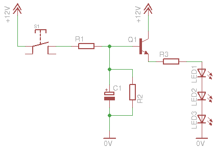
Here is the first circuit schematic that i designed, and i tried to keep it as simple as possible:
Similar to the LED fade out dimmer, multiple LEDs can be connected in parallel with one resister per node. Again, you need to take into account the maximum ratings of the transistor before connecting a million LEDs.
The circuit on a breadboard for test
The operation is as follows. When the pushbutton is pressed, the capacitor starts to charge through R1. For now, we will not take into account R2, which is at least 7 times larger than R1. While the voltage across the capacitor raises, the same happens to the base of the transistor as well. Gradually, the voltage across the LEDs is raised. When this value reaches the lower LED forward voltage, the LEDs will turn on very dim. But the capacitor's voltage still increases, and the same happens to the voltage across the LEDs, and so the fade in slowly.
The opposite will happen when he button is released. The capacitor will now start to discharge through the parallel resistor R2. The LEDs will fade out slowly, until they are completely turned off.
This circuit is ideal for applications that simplicity is needed. Yet there are some things that you need to take into consideration. First of all, the R1 and R2 resistors perform a voltage divider. If you try to reduce the fade-in time by increasing the R1 value, this will have a negative impact on the total voltage that can be delivered to the capacitor. A reduced capacitor voltage means reduced base voltage on the transistor, and in turn this means reduced LED voltage. Same will happen if you try to reduce the discharge time by reducing R2.
What this means, is that you can only make small changes to one of the R1-R2 resistors at a time. It is wise to keep R2 at lest 7 times larger than R1. You can experiment with the fade-in-out times also by increasing or decreasing the capacitor's value. In general, this circuit is not very easy to change the times.
But the major disadvantage of this, is the turn-on time. If the capacitor is completely discharged and you give power to the circuit, it will take some time before the LEDs start to fade in. This time depends on the C1 and R1 values. Greater RC, means more time. The values that i have chosen makes a delay of approximately 3 seconds. Which means that, if i power the circuit, the LEDs will start to fade in after 3 seconds. Why is that? It has to do with the LED minimum forward voltage. They will not light until this voltage is reached. If this is not a problem to you, then this is the proper circuit for your application.
Like many other circuits, it can operate in different voltages, but you will have to experiment yourself to find the proper R1 R2 and C values.
Bill Of Materials
Resistors
R1
Resistor 4.7 KOhm 1/4 Watt 5% Carbon Film
R2
Resistor 33 KOhm 1/4 Watt 5% Carbon Film
R3
Resistor 47 Ohm 1/4 Watt 5% Carbon Film
Capacitors
C1
Electrolytic Capacitor 470 uF 25 Volts
Transistors
Q1
BC548 Switching and Applications NPN Epitaxial Transistor
Semiconductors
LED1-3
LED 3mm white high brightness
To solve the problems - Circuit #2
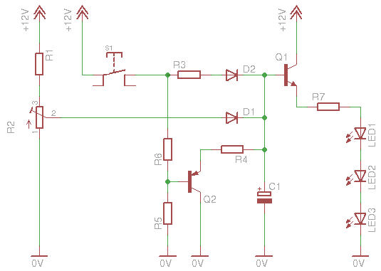
To solve the above "problems", i introduced a PNP discharging transistor to the circuit and a potentiometer to provide a constant base stand-by voltage to the first transistor:
This circuit is a little bit more complicated. Lets see how it works. And first of all, what this R2 potentiometer does. This small potentiometer is connected as a voltage divider, the output of which is driven (through a diode) to the base of the transistor. By adjusting this potentiometer, you actually change the bias of the transistor, or should i say the stand-by voltage of the base (and of course the capacitor that is connected). The fact that the potentiometer is small (500+100 (R1) max resistance) means that the RC time constant is very small. The maximum time that the capacitor will take to be charged at the stand-by voltage, is theoretically R x C = 600 x 470 x 10-6 = 0.282 seconds = 282 mSec, a quoter of a second. The usual value of the potentiometer will be somewhere in the middle, so the usual RC time constant will be about 165 mSec. So, when you power the circuit, the capacitor will be charged to this voltage within a sixth of a second.
The second circuit on a breadboard for test
Now suppose that you press the button. The 12 volts will be delivered to the capacitor through R3-D2, and it will keep on charging with a new time constant, that is R3 x C. But if you notice now, there is no discharging resistor, at least not as long as the button is pressed. Actually, the discharging resistor is the R4, but as long as a positive voltage is supplied to the PNP Q2 transistor, this resistor takes absolutely no part in the circuit. So, the charging of the capacitor (and the LED fade-in) depends only on the capacitor and R3.
Now, suppose that you release the button. The Q2 gets no more positive voltage on its base and is pulled down through the R5. R4 now acts as discharging resistor. The capacitor will be discharged through R4 and Q2. So, the discharging cycle depend only on the capacitor (of course) and R4.
What have we achieved so far:
First of all, the charging and discharging times are independent. You can adjust different fade-in and fade-out time by simply changing the R3 or R4 value. One limitation: Try to keep R3 as low as possible, maximum 1.8K. This way you will ensure that enough current will flow through the LEDs. If you need to further increase the fade-in time, you can increase the capacitor as well. So, the setup of the circuit is a piece of cake.
Most important though is what the potentiometer does. Suppose that the capacitor is fully discharged and you give power to the circuit (the pushbutton is already closed). The fade-in cycle of the LEDs, REGARDLESS the R3-C time constant, will start within less than 125 mSec, because the capacitor will be charged through the potentiometer up to the stand-by voltage! No more delay.
To adjust the potentiometer, you power the circuit WITH the pushbutton OPEN. Then, you adjust the potentiometer so that the LEDs are barely off. That is the idea. This is the stand-by voltage. You can of course do something more artistic: You can adjust the potentiometer so that the LEDs are very dim but NOT off. So, when you power the circuit, the LEDs will be very dim, when you press the button the LED will fade in to maximum brightness, and when you release it they will fade out to the dimmed level they were.
Bill Of Materials
Resistors
R1
Resistor 100 Ohm 1/4 Watt 5% Carbon Film
R2
Potentiometer 500 Ohm Linear Rotary 1/2W
R3
Resistor 1.5 KOhm 1/4 Watt 5% Carbon Film
R4
Resistor 4.7 KOhm 1/4 Watt 5% Carbon Film
R5
Resistor 220 KOhm 1/4 Watt 5% Carbon Film
R6
Resistor 330 Ohm 1/4 Watt 5% Carbon Film
R7
Resistor 47 Ohm 1/4 Watt 5% Carbon Film
Capacitors
C1
Electrolytic Capacitor 1000 uF 25 Volts
Transistors
Q1
BC548 Switching and Applications NPN Epitaxial Transistor
Q2
BC327 Switching and Amplifier Applications PNP Epitaxial Silicon Transistor
Semiconductors
D1-2
1N4148 Switching Diode
LED1-3
LED 3mm white high brightness
Need more current?
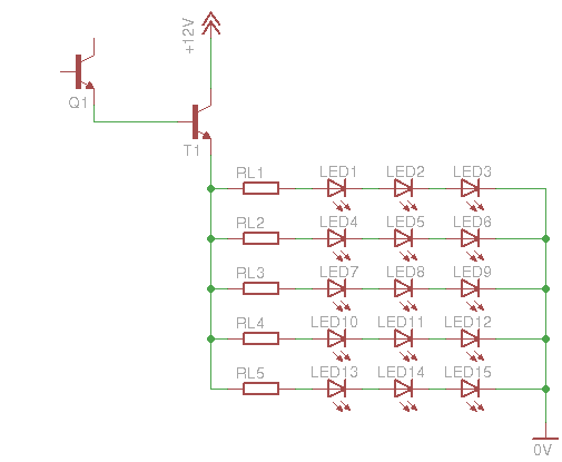
A power transistor driving 36 high brightness LEDs
If you intend to power many LEDs, then you will notice that this BC548 transistor is just not powerful enough to deliver the current you need. So you need to add another amplifying stage with a power transistor. For example, you can use the BD243 like i did. Here is a schematic how to connect this transistor. This schematic can be applied to both circuits shown above, directly at the emitter of the BC548:
Q1 is the BC548 transistor from the previous circuits. T1 is the BD243 power transistor. The above schematic has 15 LEDs (5 lines of 3 LEDs each), but you can add more lines. The limiting resistors i used are 10 Ohms, but this has to do only with the type of LEDs you will use! This resistor may be completely improper for use with other LEDs. Either calculate the resistor you need if you are sure about the specifications of the LEDs, or use different resistors and measure the current drown from each LED line (which should NOT be more than the nominal current of one LED - usually 25 to 30 mA).
At 26 November 2016, 18:05:19 user Nikos wrote: [reply @ Nikos]
Hello Giorgos,
Thanks for your post.
I would like to use your first simple circuit with a LED tape (strip), about 12 LEDs running at 12 DC.
I would like to have the same Fade in - Fade Out effect as you show us on your video.
The transistor and the others parts that I can use are the same for a LED strip?
@Tomas Schertel Nope, you have to make a proper driver for power LEDs.
At 28 October 2014, 1:20:57 user Dylan wrote: [reply @ Dylan]
I want to be able to fine-tune the fade-on and fade-off times without having to try a bunch of different resistors for my application. Can a potentiometer be used to control the fade-on and fade-off times instead of resistors? If this is possible, which resistors should I swap out for potentiometers on the "Circuit #2" diagram?
Is this circuit capable of handle power LEDs?
I'm thinking of use 2x 10W / 900mA @ 12V. Could I?
Also, do I need to use a LED driver when using this circuit? If I do need, what's the sequence of use? Driver then dimmer or dimmer then driver?
@Evangelos You can use the last version, where Giorgos say to use a BD243 to handle more current. But you can change the power transistor for a TIP41C. This allows the circuit to handle even more current.
To change fade times, you need to change R1, R2 and C1 values.
Basically, bigger C1 values means bigger charges, so, you can use more LEDs. R1 means how long to charge C1 and R2 means how long to discharge C1.
hi, what changes i have to do to the first circuit to increase fade in and fade out times to 20-30 seconds? it is for aquarium so i dont care about delay start, also i want this circuit to handle 12v 60 watt leds
At 17 October 2014, 17:52:16 user Scott wrote: [reply @ Scott]
@andrea This schematic is populated for a 12v input, experiment different resistors and capacitors to have the circuit working for your 6 volt requirement.
At 17 October 2014, 15:14:59 user andrea wrote: [reply @ andrea]
I need this circuit work With 6 volt energy
Can you give me the valor of r 1 2 3 q1 and c1
i would like to make this, but i need to make it negative triggered. (when you make a contact to ground the LED fades on when the contact to ground is broken the LED fades off)
does anyone have a way i can do that?
At 13 September 2014, 23:39:22 user Hoss wrote: [reply @ Hoss]
Nice design! How could this be modified so that instead of turning LEDs up and down, it turns a potentiometer up and down for volume fade-out/fade-in??
I would like to connect a circuit like this to a single channel of an audio mixer board. I was thinking to take apart the mixer, cut the trace of the mixer channel's volume potentiometer, and connect this circuit between the cut trace. The mixer channel's potentiometer would always be turned up where it normally would be for full volume, and the circuit would act as the variable resistor.
At 19 August 2014, 17:52:32 user herry wrote: [reply @ herry]
sorry for my bad english . i wanna ask about fading led, but it automaticly fade in fade out ?
i have 30 led blue with 3 series and 1 resistor . then how about the new schematic for 12v circuit led ?
i will apply to my motorcycle
At 19 August 2014, 9:42:33 user Razor wrote: [reply @ Razor]
actually if you place R2 between C1 and the base of transistor there will be a gradual increase in base voltage(Smoother transistion). I think then the fade in can b adjusted with R1 and R2 and the discharge by R2 alone.
Question regarding circuit #2... If I were to supply the switch and the potentiometer 5v, and Q1 12v, would Q1 emit the 12v or 5v to the LEDs when the switch is closed?
At 12 July 2014, 0:30:02 user Rene wrote: [reply @ Rene]
Is there a version of the first circuit that would work with 220vAC?
Hello, Giorgos. Fantastic site you have here, it has helped me to learn a lot in electronics.
Regarding the second version of the circuit and R3's limit of about 1K8, if I want to get the circuit say up to 2 min. fade time - this would require around 4k7/10000uf (correct?), for example.
If the problem is current to the leds, I guess the Q1 bias is affected, could we add a third transistor after D2 to amplify the weaker signal?
@Sean Not quite possible for full brightness. Its only a demo circuit.
At 17 February 2014, 22:55:21 user Sean wrote: [reply @ Sean]
If possible. How could I get this Circuit to work with a 4.5V power supply?
At 2 February 2014, 21:29:11 user steve wrote: [reply @ steve]
@Giorgos Lazaridis
Sorry, but I am not satisfied with your answer:
Please check this scheme, if You can. I tried to remove fade-out and switch:
http://imageshack.com/a/img801/9803/voue.png
The second question is general about maximmum current I can pass through BD243. It is aroud 5A at 13V.
@steve The output voltage (and not current) will be equal to VB-0.7. What is your VB? That depends on the voltage divider you have .
The current will always be Ib x hFE
@Dan It seems that you will need a higher voltage input to compensate the voltage drop. Or use less LEDs on each string.
At 31 January 2014, 9:00:27 user steve wrote: [reply @ steve]
as dvanpolanen said in http://www.pcbheaven.net/forum/index.php?topic=1601.0
I want to leave fade-out. I want to make it simplier. In circuit #2 I want to remove S1, Q2, R5, R6 and connect R4 to 0V negative. Of course BD243 is in circuit. Is it ok?
http://imageshack.com/a/img801/9803/voue.png
I will supply leds with 15V power supply. What is maximum current? 65W/15V or 65W/(15V-0.7V) ?
@Adriaan you should use higher supply voltage or LEDs with less voltage requirements
At 16 January 2014, 16:05:07 user Dan wrote: [reply @ Dan]
I am using the second schematic ( 2 transistors )
My LEDS are too dim.
I have 9.9V on the input and 8.25V at the output of Q1
When I drive the LEDs directly from the supply (9.9V) I like the brightness. Can I get the voltage at Q1 output higher than the 8.25 that I am now seeing ?
Note: I also tried the power transistor BD243 and I get the exact same brightness and the exact same voltage out ( 8.25V out )
Thanks
Dan
Hello, i'm sorry for my bad English, i'm from Holland....
I have build this for my Led lightning strip 12V 660mA, but the voltage out of the T1 BD243 is max. 8V.
How can i get 12v out of it?
I'm a beginner with electronics, so explain it easy please.. :-) (scheme?)
Thanks!
At 8 January 2014, 0:42:46 user Leon wrote: [reply @ Leon]
Hello,
I need this circuit in a quite different way to use it as an effect controller by an ldr,
I want to control 3 variables independant
- set the minimum light intensity (0 to 100%)
- set ramp time to 100% intensity by a pot
- set ramp time to 0% intensity (overruled by minimum setting)
I simulated this simple circuit on my computer but i can't get it done
Thankyou very much, with the circuit #2 all i need to change is the c1 and r1 to change the time? Is that circuit will work with high power leds too, bcus i have whole bunch of leds that connected in series with proper resistors and now i only have it turn on and off with a dc timer and i want to use the circuit #2 to fade in and out, do i need to change anything else thankyou very much for helping.
@Phillip Use bigger C1 and R1. You need to go through trial and error. Start with 2200uF capacitor and replace R1 with a trimmer of say 500K. Then do your tests.
@Matt The way you describe it looks like you have to add all LEDs in parallel. Make sure that each LED has its own resistor.
At 9 November 2013, 3:08:05 user Matt wrote: [reply @ Matt]
I'm looking to have a circuit of 19 blue LEDs (3V fwd voltage, 20mA fwd current) automatically fade in and out, and I'm probably going to end up using a phone charger or other household transformer to power the circuit since batteries don't seem to be very feasible. A charger that I have on hand carries 5V at up to 850mA. What kind of configuration would I want for my circuit to get this work? Would I end up just adding more parallel sets to the picture directly above (19 LEDs instead of 15)? If so, I'm not quite sure how that picture fits into the rest of the circuit.
hi,
I'm building a small starry sky with only LEDs.
I would use four of your circuits to create effects to the sky using three or four LEDs on each circuit.
I would like to replace the button with four timers 555 set with different times. (very long 4/5 minutes)
What do you think? The 555 output current is enought?
thanks
Sir I would like to ask permission to used your LED Fade-In Fade-Out Dimmer for one of my basic electronic laboratory exercises for my class. I am teaching Basic Electronics in college.
Excellent fading of LED strip with a push button. Since I'm a begginer I can't trigger the circuit with a PIR sensor (3.3V). Tried different transistors but no luck. Can you help?
is it possible to modify the circuit to light up the LED one by one sequence? e.g. LED1 on --> LED2 on --> LED3 on --> release the switch --> LED1 off --> LED2 off --> LED3 off
At 19 June 2013, 10:27:26 user bill wrote: [reply @ bill]
how could this circuit to operate with a time 30 to 40 minutes; ie takes 30 minutes to complete Powering and 30 minutes to complete off
@Liam C1 discharges through the resistor without any power.
At 27 May 2013, 11:50:56 user Liam wrote: [reply @ Liam]
Hi,
I understand how the C1 discharges back through the transister which has power constantly.What I'm trying to do is much the same but have the C1 (which can be parallel banked capacitors) discharge whithout any power input into the circuit.
So once SW1 is open, power in is 0v. So in a nut shell no transistor.
Is there a way I can 'modify' this circuit to do that by just removing the tansistor or will the discharged voltage just be too low?
Oh I'm using 4700uF 16v caps.
Thanks for your time
What would happen if we were to get rid of R2 in the first simple circuit? Wouldn't the capacitor still charge and then discharge through the transistor?
@JIM I'm not quite sure if the current provided is enough. Use the first circuit with a second darlington. Also use at least 2 volts higher voltage than the motor voltage.
At 2 May 2013, 19:28:31 user JIM wrote: [reply @ JIM]
I love your fader circuit. I have tried to duplicate it with no success...but here is what i am trying to do.
I am using a 5 volt system and instead of using an LED to light, i want to have the voltage slowly fade in to 5 volts and maintain to operate an air core motor (needle will slowly move to maximum) and then when the contact is broken have it fade out with the needle slowly going to zero.
is this possible with modifications to your original circuit...and if so can you provide details.
@josh In that case you will need 2 555, one for the fade and the other for the pulses.
At 22 February 2013, 20:09:31 user josh wrote: [reply @ josh]
Is there an easy way to integrate a 55 timer to have a variable pulsing, instead of a switch. I need something that slowly and constantly pulses the same way the second circuit with minimum brightness does, but to be constantly pulsing
At 16 February 2013, 20:20:18 user Mike wrote: [reply @ Mike]
I can't get it to work either way and I also tried with a few different configurations. I think I am going to have to use a SSR IC. I can get it to light up an LED but not when the switch is open... it lights when the switch is closed. So I am not sure what to do to fix it.
@Mike add a 220K pull-down resistor from Q1 base to ground. delete the 220K you have right now. The emitter of Q2 goes to ground. the positive of your sound board goes to 3.7. The negative goes to the emitter of Q2
At 11 February 2013, 22:19:19 user Mike wrote: [reply @ Mike]
Giorgos,
Thank you for the reply. That is interesting. I think if I could find an IC to do the job it would simplify things but I am glad to know that it can be done without one. Just to make sure I understand I drew out the schematic. Here is a link to view it:
http://sdrv.ms/X3iQSV
And with this circuit when the switch is closed then Q2 is 'open' and pin 18 is not connected to ground (3.7v circuit). Then when the switch is open, Q2 is 'closed' and connects pin 18 to ground (3.7v circuit). Is that right?
@Mike @Mike So, you want an inverting circuit. Use another NPN transistor, the base f which goes through a big resistor (10K or bigger) to the S1 output. The emitter goes to ground. The collector through a 4K7 resistor goes to 18V. Then use another NPN, the base of which goes between the 4K7 and the collector of the previews transistor. Use the rest of this transistor as a switch for your buzzer.
At 8 February 2013, 17:12:42 user Mike wrote: [reply @ Mike]
Giorgos,
I am sorry for the confusion, I really appreciate your willingness to help out. Let me see if I can explain better what I want to do.
I have a reed switch (S1 in your diagram) that I trigger with a magnet that turns on the LED circuit. Currently I am using a 2n3904 transistor that acts as a switch to trigger the sound effect on a separate sound module. The sound module runs off a separate 3.7v power source. When I close the reed switch the 18v is sent through the LED circuit and also goes to the base of the transistor which passes through the 3.7v from pin 19 on the sound module to the ground on the 3.7v circuit to activate the sound. I also have a 220k resistor connected from the Emitter of the NPN transistor to the ground on the 18v circuit otherwise the transistor would not work.
What I want to do now is a little different. I still want to trigger the sound when I close S1 but I also want to trigger a sound when I open S1. I can do this with a SPDT relay but a regular relay makes a clicking sound when it is activated. I heard about an IC that can do the same thing without making the clicking noise. I believe they are called Solid State Relay ICs or Swich ICs.
The way it should work is that when S1 is open the IC is closed on pole 1 which is connecting the ground on the 3.7v circuit to pin 18. When S1 is closed then the 18v will trigger the IC to switch to pole 2 which will connect the ground on the 3.7v circuit to pin 19 and activate sound 1. Then when you reopen S1 the IC will switch back to pole 1 and reconnect the ground to pin 18 on the sound module and activate sound 2.
I am having trouble finding information about this type of IC... my local electronics supply store doesn't stock anything like this so I will have to order them online. If you have a suggestion I am all ears. Any help you can provide would be very much appreciated.
@Mike I think i got it the wrong way. So, you want to build a switch to turn on and off something that....???? It has a button to activate the sound and you want to bypass that button? Or you want to turn on and off the module's supply?
@Fred Quimby I'm sorry but i do not do circuits on demand.
At 5 February 2013, 18:15:01 user Mike wrote: [reply @ Mike]
Giorgos,
I looked into a comparator but from my quick read on it I don't understand how that would work. It looks like a comparator is used to switch something on/off when the non-inverting voltage is higher than the inverting voltage. All the example circuits I saw did not indicate that it could switch voltage from one pole to the other as a SPDT relay would. If I am wrong then please let me know.
@Fred Quimby Actually, this circuit may not help you at all. If you connect a capacitor to supply and then you power an LED from the capacitor with a series resistor, you have the off delay that you want. As simple as that. The size of the capacitor will determine the off delay. You may need to have a zener diode (like 5.1V) before the capacitor to regulate at 5 volts.
Thank you, perhaps I should start small and just look at having the front and rear lights stay on for a while after power is removed. I guess I'm looking at adding a capacitor somewhere near Q1, with the capacitor being powered when there is a voltage and the disipating it's power through the transistor to the LEDs when power is removed.
Am I on the right track ? I have a feeling that there will need to be another transistor in there too.... at this stage I'm happy to receive a BIG hint
@Fred Quimby What you ask to do is not very simple. It would be easier to have a small rechargeable battery (if fits in the car), or a large electrolytic capacitor, or probably a super-capacitor. Then you need some sort of voltage regulation which can simply be done with a zener. I suppose that all lights are LEDs. Keep the LED current low to have less power dissipation.
Then you need a comparator for the breaks. The breaks will come ON when the voltage drops bellow a certain threshold (you chose).
If you choose the capacitor solution (which i recommend), the dim-off function will be standard when you remove the power. The only problem is that you have to tweak LED currents when breaking, because the break LEDs may drain the current from the capacitor and the lights will dim.
It all does not sound too hard,but it will certainly be bulky.
@Mike The 3.7V will still be a problem. You need to solve this first. How about a comparator instead? Which will give a HIGH output when the voltage becomes higher than a level (lets say 5V). It is much cheaper too
Hi, I think the message I sent you must have got lost in your troubles. I hope that you site attack problems are over.
A slot car is an electric powered car that runs on a plastic or wooden tract, with a guide blade in a slot, where it picks up the power they generally run between 9 - 16V with 12v being the norm (Scalextric).
I would like to fit some LED's front and rear for head and tail lights, and another two read leds for brake lights.
The idea is that I want the head and tail lights to remain alight even after the power is removed from the track or the car is removed, for a while so I need to understand what I need to do this. Not sure what a while is but the smallest capacitor with the longest time possible is idea. I would also like to use a voltage regulator IC7805 so I don't have to worry about if it's a 9 12 or 16v track.
The brake lights I see as being the big challenge as I would like them to come on when there is a voltage drop, but that may not be down to less than 5v, so somehow I will need to factor that in, it might even be a completly seperate circuit, but it would be good if it could be intergrated into the whole. What I would like to do here is something like if the voltage drops 20% apply the brake lights and keep them on until voltage goes back up to max, something like that. Now the problem here is again 9 12 or 16v tracks, so how do I decide the max and the <20%. That could be a challenge too far for me, but I'm interested. With slot cars i think most people will just let go if the throttle to slow down, so the power to the track would drop to 0v when braking and I'm sure I could use this to apply the brake lights, but it would be nice to be able to do the more sophisticated trick I suggested above if it's possible.
I've set this as a challenge to myself really but since I have the came amount of electronics knowledge as will fit in a pin head this might be easy for you but it will be all learning for me. I don't want to have you tell me and show me everything, but I do need help on what I need to consider, what I need to understand, and anything that does simular so I can work out and understand it better.
I look forward to your reply and hope you will help me with my challenge.
At 30 January 2013, 16:19:11 user Mike wrote: [reply @ Mike]
Hello again, If you recall I am using this circuit in a custom application with 18v in so that I get 14v to the LED array. I also have a sound being triggered at the same time the switch is closed via another NPN transistor as the switch for the sound module.
I now want to trigger a sound when the switch breaks as well as keep the sound when the switch is closed. So I tried to use a PNP transistor as a N/C switch but it didn't work because the sound module is powered by 3.7v so the base voltage is always higher.
I think I need to use a solid state relay IC or a switch IC. I think this can be used to replace the NPN transistor that triggers the first sound as well as triggering the second sound when the switch breaks. So I am looking for a SPDT IC that will have to have isolated passthoughs for the throws. In other words, the 18v will trigger the IC to switch from one throw to the other but the throws will be passing through the 3.7v not the 18v. The 18v has to be separate. Just like on a regular relay. But the clicking noise of a regular relay is too loud.
Can you suggest an IC that would work in this situation? I would very much appreciate your help. Thanks.
Thank you for your reply, it seems it wasn't a capacitor problem, but user error...... Check , then check then check again...
Now onto the next version. I eventually want to have this run so that I can put another capacitor in where the 12v is to the collector of Q1. The idea is to eventuall use this to put in a slot car so that when the power is removed from the track head, and tail lights stay on for a while, if you have any tips more than happy to ready about them.
Good night.
It's possible to use this circuit in a strip of led's?
Can i turn on or off the strip of led's with fade in and fade out, ignoring push button?
Thanks a lot and sorry my english and congratulations for the good explanation
Firstly, i feel very happy to see your post when i search this circuit ... so i have a few question please give me an answer if you can :)
1/ what will i do if my power supply is 24 volt ( car )
2/ i want to make the circuit just fade-in and NOT fade-out,how can i do this ?
thank you very much :X
@Eugen Different LEDs have different Vf: http://www.pcbheaven.com/wikipages/LEDs
At 12 December 2012, 19:22:27 user Eugen wrote: [reply @ Eugen]
HI there,
i have a little question.
for 3 white leds you use 47ohm rezistor, that means the forward voltage is 3.6.
an a website i read this: " Red and green: 2 volts, Blue and white: 3.0 - 3.5 volts and forward current is 20mA ".
so i can use this values:
1xRed/Greed led: V=2V, I=20mA and 560 ohm rezistor; 3xRed/Greed led 330 ohm rezistor?
1xBlue led: V=3V, I=20mA and 470 ohm rezistor; 3xRed led 180 ohm rezistor?
1xWhite led: V=3.6V, I=20mA and 470 ohm rezistor; 3xRed led 47 ohm rezistor?
@Mike yep, increase both to maintain same voltage, and may need to change the capacitor
At 20 November 2012, 14:26:32 user Mike wrote: [reply @ Mike]
@Giorgos Lazaridis I just wanted to ask one more question. With my setup (18v power source) R2 is getting a little too warm. How can I account for that? Since it is acting as a voltage divider, increasing the value of R1 would reduce the 'strain' on R2 in turn reducing the amount of heat produced, right?
At 16 November 2012, 18:34:39 user Leigh wrote: [reply @ Leigh]
Thanks for designing and sharing the LED fade-in fade-out dimmer circuit. I just built a version that works well. One thing that is happening with my prototype is that the fade-in is much shorter than the fade-out time. I like the duration of the slow fade out, is there anything that I can modify that will extend the fade-in period?
@Mike This is a question that cannot be answered simply by numbers. It depends in many parameters, led forward voltage, number of leds, max and min current through led, desired power dissipation on transistor and many more. You need to make experiments and calculations.
At 10 September 2012, 22:28:42 user Mike wrote: [reply @ Mike]
@Giorgos Lazaridis Would you recommend changing the values on any of these resistors considering I am using 18v? What values would you use for them? Would this improve efficiency?
@Mike this transistor works basically as a switching transistor, so anything above 1V will work. I used big resistor only to minimize the current. At 18V i'm sure that you can use much larger resistor if you want as well. In any case, i'm not surprised that it worked. normal.
At 29 August 2012, 16:14:24 user Mike wrote: [reply @ Mike]
@Giorgos Lazaridis Thanks, I just might do that and if so I will, of course, give you credit for this circuit.
Question for you... I think I made a mistake but the circuit still seemed to work ok which is why I did not realize it until I was making a list of components I used.
R5 is supposed to be a 220K resistor as part of a voltage divider. On my circuit I am putting 18v in which means the base of Q2 should be getting about 15.7v per the design on this circuit.
My mistake is that I am pretty sure I used a 220ohm resistor for R5 instead of a 220K resistor. This means that the base of Q2 is only getting 7.2 volts.
How will this impact the function of this circuit? As I said, it still worked but I am wondering if it is further limiting the voltage getting through T1 or if there are any 'side effects' that this is causing?
@Mike excellent. why don't you post your make in our forum? and the circuit schematic? others may be interested for this as well. many people want to make an LED fader.
At 24 August 2012, 15:51:21 user Mike wrote: [reply @ Mike]
@Giorgos Lazaridis Thanks for all your help. I have made a voltage boost DC-DC converter from the LM2577-ADJ voltage regulator. It is taking my 6v battery power source and boosting it to 18v. I have connected it to supply power to the whole fade-in/fade-out circuit as you said and it is working just fine. I also initially tried to test it connected only to the power transistor but that did not work which makes sense now that I think about it.
This voltage regulator also has the added bonus of maintaining full LED brightness through the life of the batteries (LEDs will maintain full brightness until batteries run down to 3.5v). You can also use various power sources between 3.5v - 16.5v without effecting the end result (power through the fade-in/fade-out circuit). So this is a big help for anyone that needs a portable setup.
Anyways, I just wanted to write back and let you know and to post this info for anyone else reading. Again, thanks for all the help.
@Mike what you say is true, and this is how the circuit is supposed to operate. at higher voltage, there is enough voltage for all the components (transistors diodes) to drop and still have enough voltage for the LEDs.
You can indeed make a boost regulator for power source. To incorporate it, simply replace it in the place of the power in the circuit.
At 20 August 2012, 16:08:09 user Mike wrote: [reply @ Mike]
@Giorgos Lazaridis So this circuit is working as it is intended but one thing I noticed with using a lower voltage and fewer batteries is that the LED brightness seems to be effected by varying the resistance a lot more than it was when I was using 15v. Also, the LED brightness gets noticeably dimmer as the batteries drain. Using single resistors in front of the LEDs just doesn't cut it when the voltage/current changes so much.
I have been thinking of using a boost IC with a constant current function that would boost the voltage up to the necessary level and supply a constant current to a G4 LED disc that is designed to run in cars and boats. Using this G4 disc would make things easier too not having to make a pcb for the LEDs and solder each one with a resistor.
This is the ic I was looking into:
http://www.instructables.com/id/Switch-mode-LED-torch/#step1
However, I am not sure how to incorporate it into this circuit. I am not sure if it would be best to supply the whole circuit with the stepped up voltage and adjust the current for the whole circuit, just supply the collector of the power transistor (T1) with the stepped up voltage, or connect the boost ic after the emitter of the power transistor (T1). I would love to get some advice on which of these options is possible and/or which is the best solution. Of course if you have a better suggestion I am all ears. Thanks again... you have been a big help.
At 12 August 2012, 5:39:25 user Mike wrote: [reply @ Mike]
@Giorgos Lazaridis Yeah, it looks like these comments don't support HTML. If you copy the first web address listed and paste it in the address bar then hit enter the image will come up. Most browsers nowadays will allow you to just highlight the address then right-click and select 'open link' or 'open link in new tab' etc.
@Mike image not found :/ why dont you upload it better in out forum pages?
At 8 August 2012, 17:04:31 user Mike wrote: [reply @ Mike]
@Giorgos Lazaridis Ok, I got it figured out so I just wanted to share my circuit variation with everyone here. I took this LED fade in/fade out circuit and modified it to add a reed switch and to give the circuit adjustable fade in and fade out times (adjusting the fade times will directly effect the brightness of the LEDs). I also added a 'trigger' for a sound module.
Normally you would press a button on the sound module to play the sound effect, music, voice, etc. With this circuit you can trigger the sound module at the same time as the LED effect. All you have to do is wire the positive side of the play button to the collector (C) of Q3 and then wire the negative side of the play button to the emitter (E) of Q3.
I do not know if both R9 and D4 are necessary but they don't seem to be hurting anything. Here is the modified circuit diagram:
@Mike bc548 can handle 100mA indeed. you need something bigger. as for the reed, i suggest before you connect it, put the ammeter and see what current will go through the reed. I cant think anything else.
At 5 August 2012, 3:58:52 user Mike wrote: [reply @ Mike]
@Giorgos Lazaridis I just thought of something. I can't say for sure but it is possible that I might have connected an active power source to my breadboard during testing that might have caused a voltage spike that damaged the switch. I don't even know if that could/would happen but it is a theory. It is either that or a defective switch unless there is some other unseen variable that is beyond my knowledge.
I am going to use one of the other reed switches on the circuit tomorrow to see if that works. I will be careful not to connect it to an active power source, etc. If it goes bad too then there has got to be something else going on that I can't figure out. If not, then it was probably on of the previously mentioned culprits. If you have any other advice or opinions then please do offer them. Like, for example, do you think I should hook up the diode after the switch as previously mentioned?
About the BC548, am I correct in reading the datasheet that it can only handle about 100mA of current? If so, than I guess I do need the power transistor. Thanks for all your help.
At 4 August 2012, 19:26:13 user Mike wrote: [reply @ Mike]
@Giorgos Lazaridis Yeah, it is pretty obvious that this circuit didn't get anywhere near the max limit for the switch. Arcing is the only thing that could have caused the reed switch to stick. Maybe it was a fluke... a defective switch. I have been nervous to try another reed switch at the risk of 'breaking' that one too.
Do you know much about how to use reed switches? Is there anything I should add to the circuit to protect the reed switch? The only thing I can find is that on inductive loads you should use a diode connected parallel to the load. In this case how would I do that? I believe the cathode should connect right after the switch and then the anode would be connected to the negative rail right after R5. Does that sound right?
Here is a link to that protection advice. Look at figure 1 on page 2.
@Mike obviously, the circuit works. the inrush current of the cap cannot be larger than i=v/r = (6-0.6)/220 = 24mA, without calculating the per-charge from R2. One guess i can make is that you could mistakenly have connected the anode of d1 with r3??? This is the wildest guess i can make. I cannot think of anything else.
At 4 August 2012, 16:34:25 user Mike wrote: [reply @ Mike]
Here is a little extra note. I just hooked up the relay and it works perfect for activating the sound module but I measured the current through the switch to activate the relay and I am getting .15 Amps. This is more than I was getting for the switch directly connected to the circuit. You can also hear the clicking of the relay. That is not good. It pollutes the sound coming from the sound module.
Man I really want to use the reed switch. How can I hook it up so that it won't get stuck?
At 4 August 2012, 16:00:15 user Mike wrote: [reply @ Mike]
@Giorgos Lazaridis Ok I checked the current the right way. :D However, I couldn't get the mA selection on my multimeter to work. I always got a 0. I had to use the 10A selection on my multimeter. Anyways, with 6v power source I was getting .01 Amps through the total circuit using the one 5mm led with a 100ohm resister (smallest I had, should have been 68ohm). I got this reading both on the bypass and when the switch was activated. It was also the same reading through the switch.
I hooked it up to a 12 battery pack and used a G4 LED disc with 12 5050 SMD LEDs (4 parallel rows, 3 in each series, four 120ohm). I then checked the current on this setup and I was getting .05 Amps through the whole circuit and .02 Amps through the switch.
So now I am entirely confused. This is nowhere near the 500mA rating on the reed switch. Why would the contacts have weld together? Could the capacitor or something else in this circuit be causing a inrush of voltage?
At 4 August 2012, 3:50:10 user Mike wrote: [reply @ Mike]
@Giorgos Lazaridis Oh, yup. I was measuring the current the wrong way. I will take the current reading the right way tomorrow morning and post back the results. I thought that there had to be something wrong for this circuit to be pulling 5A or even 500mA. ;)
I purchased a couple relays to use that will isolate the reed switch from the circuit. According to the information I found I must also put in a diode parallel to the relay coil. To be honest I think I would have needed the relay anyways to switch on the sound module. As I said it would only play when the button contacts were bridged. So I will have to send one side to the common on the relay and the other side to the NO side. The relay I got is a DPDT so it can do both the circuit and the sound module.
I would just really like to know why did the reed switch weld if it was only getting like 80mA? The only two causes of the stuck reed that I could find are if the current was too high (500mA max for the reed) or if there was an inductive load that causes a high in rush of voltage causing the contacts to arc before they connect.
I was also wondering if I even need the power transistor if the LEDs are only pulling 240mA (720mA if I use 5050 SMD LEDs).
Ok, so I will correctly measure the current and get back to you. Thanks for your help.
@Mike the numbers you are saying are insane! With max 12V supply, suppose that R3(220) and R6 (330) were grounded - the equivalent Rtot would be 152 ohms so max current would be 79mA, which is WAY less than 500mA. So something terrible wrong is going on.
As for the current measurement, the way you describe it is wrong. You just measured the maximum current that your supply can provide. If 5 amperes go though the circuit, there will be mayhem! To measure properly the current, do this: Make the circuit, and then cut the positive line of the supply. Then connect the red of the ammeter to the of the supply, and the black to the positive supply of the circuit. This way you measure the TOTAL current, including the 25mA of the LEDs.
To measure the current through the switch, simply remove the switch and put the ammeter in the place of the switch (positive to one side and negative to the other). The current must be in the scale of a few mAmps, not more...
At 3 August 2012, 14:23:09 user Mike wrote: [reply @ Mike]
Oh forgot to mention that I can't find much information on hooking up a reed switch via a relay but I did find a bunch of info on using a Mosfet to switch power via the reed switch. However all the diagrams show the load on the high side and the Mosfet on the low side and that won't work with this circuit. Or at least I couldn't get it to work... in order to fade out the ground has to be connected and when the Mosfet is turned off it disconnects the ground. Maybe there is a way around this to use the Mosfet on the high side instead or maybe just a different way to connect it to the circuit that won't interrupt the ground path for the fade out.
At 3 August 2012, 14:16:10 user Mike wrote: [reply @ Mike]
Hello again,
I built this circuit a year ago with your help and it has worked out great. I am at a point though were I want to change the way I activate this circuit. In my application the push-button is difficult to activate easily and reliably. I want to use a reed switch. I tried to hook up the reed switch directly in place of the push button but I ran into some trouble with that. First, let me give you some info. I have this circuit set up on my breadboard but I also have changed R3 and R4 to some trip-pots. R3 now has a 220 Ohm resistor and a 1K trimpot and R4 has a 1K resistor and a 10K trimpot (I was going to go with a 5K trimpot but the local shop didn't have any). I am also using a 5A power transistor for T1.
I originally built this circuit at 15v using 10 AA batteries but I am trying to make it a little more mobile by dropping it down to 6v using 4AAA batteries. For testing purposes I had this circuit hooked up to one LED (eventually it will power 12 5mm LEDs, 3.2v 20mA each and each will have an SMD resistor).
Ok so with this setup I used the reed switch but after only a few seconds and a few activations the reed switch contacts weld together. This indicates the current is too high. I was wondering how many amps should this circuit draw with only one LED drawing 20mA? I was using a 220 Ohm resistor in front of the LED(I originally had it hooked up to a 9v battery). I took a current reading with my multimeter, positive line connected before the switch and negative line after the whole circuit on the ground to the battery and I think it said I am drawing around 5A. Is this right? Is it because of the power transistor? Will it always draw 5A no mater what is hooked up to it? Do I even need the power transistor for 12 LEDs at 20mA each = 240mA?
One more question, how can I hook up the reed switch so that it wont burn out? It is rated at 500mA max. I didn't think there was that much current going through the switch. Should I use a relay with a diode wired in parallel to protect the reed switch? Any help you can offer would be greatly appreciated. Thank you.
@Roger some 2 months ago i made one similar with a PIC. To tell you the truth, it was not easy to achieve a smooth fade. There are some tricks though with 2nd and 3rd degree equations (x=y^2 for example) that will make it smoother, still not as smooth as this.
Do you think its possible to get the smooth fading using a PICAXE ? Thats the extent of my micro controller experience and I really want to get this effect with a small one of 2 component setup with minimal standby power draw.
@nikolaos i'm talking about 4700 or 10.000 uf, not large in size, but relatively large for RC timing circuit. It will require also a large resistor, so any slight variation to these two will result in a large error. That is the problem
If you do not want to work with microcontrollers, then go for a digital circuit. A crystal oscillator at 32.768 KHz with a 256 divider and another 128 divider will give you a very precise 1Hz. You can then put a counter to activate your fade-in and fade out circuits.
@Giorgos Lazaridis
Last question, sorry to bother you again but microcontrollers and stuff are not my thing. Or is there something simple your thinking about ?
@nikolaos the error will be accumulated. If for example the error for 24 hours is 3 minutes, the next day it will "sunrise" 3 minutes later, the next day 6 minutes, the next day 9 etc... Large capacitors are very unstable and are sensitive to temperature.
@Giorgos Lazaridis
What exactly do you mean ?
If you mean that the duration of the <sunrise> is 30 min. one day and the next it is 25 min. and then the next its 30 again, then it really is no bother. Even in nature the time varies due to clouds e.t.c.
You don't mean 5 min less every day, do you ?
@nikolaos for such situations i definitely advice people to use microcontroller-based or other digitally based circuit. Trying to adjust an RC circuit for long periods is usually not possible... Unless you do not care if every day you have some 5 minutes time loss
Hi Giorgos
I want to light my aquarium or my birdcage e.t.c. with led strips. The circuit must have fade in and fade out times close or similar to sunrise and sundown. Anyway a good time for fade in would be about half an hour and the same time for fade out. From my 220V timer i supply a 12V adapter to drive the leds. Can this circuit with some modification or a similar circuit give me these times ?
Thanks in advance.
Thank you for providing this fantastic tutorial. I am working on a project that will do something similar to this but different in one major way: Instead of fading in and out, I would like to construct a circuit where the LEDs simply flash to full brightness and then fade out. Do you have any suggestions for this type of circuit?
@Roger You want this circuit for battery-depended application? how much current i draws in idle mode? it should not be that much! I suppose you talk about the second circuit with the 500 ohms potentiometer. That should draw about 12/(500 100) = 20 mA throygh the potentiometer. You may wanna try a iger potentiometer, but it will be les reactive to changes. Try for example a 5K potentiometer instead (for R2) which will drop the idle current down to 2.3mA
I really love this circuit! Made it back in October but I really need to find a way (or alternative circuit) that doesnt drain as much current in "idle" mode. Any suggestions?
@Darren 30-12 = 18 volts at 320ma=5.76 watts of dissipation on the transistor. It is absolutely normal that it will get too hot. anything above 2 watts is already enough to heat up the transistor fast. What you can do is reduce the input voltage to nearly the voltage required by the LED - for example you need 12 volts on the led? use 14 volts supply.
Hi, i'am using the circuit to power-up a LED downlight,the source from the LED power driver is about DC 30 volts (320mA), the BD243 is extremely hot(with heatsink). What should i do? Thanks
@Annonomous you will need certainly to add a power transistor (as explained in the document) and a heatsink. I cannot tell you more. You have to do some tests.
Hello I am in middle school and i want to put some led light strips in my locker that fade in when i open the door. I was wondering if i need any different components for a led light strip I found here.
@Jon strange indeed. sign up in the forum and send me the manual as attachment
At 9 February 2012, 15:46:25 user Jon wrote: [reply @ Jon]
@Giorgos, I got very strange result. First, when the PIR is INACTIVE (live but not sensing motion difference), the OUTPUT reading shows 10.36V. However, when the PIR is active (i waved my hand), the OUTPUT reading shows 10.45V.
Based on the PIR datasheet (how can I send it to you?), it is active LOW but yet I don't see this behaviour in the output. The LED does shows brighter and it is INACTIVE and dimmer when the PIR is ACTIVE (contradicts with the Voltmeter reading). How can I test if the PIR is working or faulty?
On the other hand, when the pull down resistor is connected, the OUTPUT reading shows between 0V and 0.22V.
@Jon Oh, i see what is the problem here. The output does not go lower than 2.5 volts. 2 things you should do and reply: First, measure the voltage with multimeter for the 2 different states of the PIR, and second, instead of a pull-up use a pull-down and tell me the results. We will sort it out.
At 7 February 2012, 10:46:44 user Jon wrote: [reply @ Jon]
Hi Giorgos, thanks for the advice. My previous connection is quite similar to your proposed connection. I had connected the LED strip on the collector instead of the emitter. By doing so, the LED strip will have the full 12V across it instead of the 0.7V drop on the emitter. Is this advisable? I have, however, wired up the proposed connection and found the result are the same regardless if the LED strip is connected to the Emitter or the connector. The LED strip remains lit (same level of intensity) regardless of the PIR state.
Thus, I fall back to the basic connection which is just a pull up resistor and a single LED (not LED strip) to the PIR output. The LED does shows visual difference. When the PIR is inactive, the LED is bright. When it senses motion from my hand, it becomes dimmer. However, I do not find this differences in the LED strip. Could you advise what should I do?
@Jon You need an amplifier, probably an emitter follower to get maximum current. Connect the base of the transistor to your output (with a pull-up resistor around 470 Ohms or 1K). The collector is connected directly to the power supply of the strip and the emitter directly to the strip positive. This will get you enough current for the LEDs, only that the output will be about 0.7V less than the input.
At 7 February 2012, 6:29:45 user Jon wrote: [reply @ Jon]
Hi, you are amazing. Could you help me on this design?
I'm intending to use a PIR to control the LED strip. When there is someone in proximity, the LED strip will fade in and after a couple of secs when no one is there, the LED strip will fade out.
I have a PIR with a open collector output and I have connected a pull up resistor to the output lead. I have realized the OUTPUT is too weak to power up the LED strip. If a normal LED is connect to the OUTPUT lead, i could see the light but not when LED strip is connected to it. Could you please advise how should it be done? Thanks.
@vimal it is not for 1 LED, it is for 3 in series with a resistor. The output voltage shifts up to (around) 1v bellow the supply voltage (which is 12V). If you read the complete page, i add a BD243 to increase up to 6A the ouput. You may use a bigger transistor to increase further more. As for the lower voltage, prototype the circuit on a breadboard and you will find out how to use the potentiometer.
Hello. I was wondering if you could help me. Is there a way to make the fade-in and fade-out times 3 minutes or higher without reducing the current. I am planing on using the first circuit with 12v psu running 2 LEDs.
At 6 November 2011, 5:50:02 user vimal wrote: [reply @ vimal]
wow.........thats 95% what i was looking for.great work man.
your circuit is for one led only.in fact i want such circuit because i wanted to put led lights beneath my car,i will use led strips for that.
(1) but the led strips uses around 6amps at 12v.how should i modify the circuit so as it can power the led lights at 6amps.
(2) your circuit uses 5v,is there a way to use 12v to power your circuit?
(3) i dont want the lights to fade out completely,how can i use a potentiometer to do that
i know i am asking a lot but i wanted such circuit since 2 years.please help
@vimal try this one instead:
http://pcbheaven.com/circuitpages/555_Breathing_Pulsing_LED
At 5 November 2011, 19:42:31 user vimal wrote: [reply @ vimal]
hello friend,nice experiment.
i would like to ask you something.is there a way if i want to make this circuit to work automatically with a 12v car battery.meaning,adding a potentiometer to adjust fade in and fade out at equal time intervals without the press button.
simply, what i want to make is a circuit like the last one in your video with the power transistor and with leds with 2 changes.
(1) eliminate the press button so that when i connect the curcuit to the battery,it starts fading(i think it should work with a timer)
(2)a potentiometer to adjust speed of fading in and out
is it possible to make?please help me.
At 19 October 2011, 13:13:16 user Steve wrote: [reply @ Steve]
Hi, i was wondering if you could help me, ive set up a series of lights under my fishtank top hood and have red green and blue in sequence on a light bar, white leds on a light bar and on a seperate circuit four dichoric 12v warm white led downlights.
So ive basically got three individual lights groups all 12v and wanted to know if you have ever heard of any way to fade randomly between the three groups slowly, to give it a different fading/changing colour effect?
Cheers
Steve
@Mike there will be no problem if you power with 15 volts. a relay will not work at all, you need to have this power transistor.
At 8 October 2011, 20:46:59 user Mike wrote: [reply @ Mike]
Kammenos,
Oops one more question... I went ahead and build this circuit on a breadboard and tested it. It seems to work fine. One thing I noticed that the value of R3 directly effects the brightness of my LEDs... the lower the resistance the brighter they are. If I connect this circuit to a 12v power source (batteries), then the LEDs only get about 10v. With the 220ohm resistor you recommended and the 2k trimpot adjusted to give a decent amount of brightness at the expense of a shorter fade-in time the value of R3 is about 330ohms. I am not sure if there is a better way to get more power to the LED Array but I am thinking about putting more than 12v in the power source. I went ahead and added another 1.5v battery bringing the power source to 13.5v and the LEDs now get about 11v and are much brighter. They are still not to their full potential since they are designed to work on 12v. If I add another battery (1.5v) and bring the power supply to 15v it should increase the voltage to the LED array to about 12v. However, I do not know how this would effect the longevity of the circuit components. Is this a plausible course of action or is their a better way to get 12v to the LED array? Maybe a relay would work better than the power transistor. Let me know what you would do. Thanks.
@Mike i cannot tell you because i do not know these transistors, never used them before.
At 8 October 2011, 14:20:06 user Mike wrote: [reply @ Mike]
Kammenos,
Thanks for the fast reply and the advice on using the small resistors in series. I have one more question for you. They didn't have the transistors you specified at my local shop but they did have some substitutes. I wanted to run them by you before I turn the circuit on and see what you think. Instead of BC548 they gave me NTE123AP. They substituted BC327 with NTE159. Also, they didn't have the BD243 power transistor, their computer actually recommended NTE377 but they didn't have that either. The computer also listed NTE331 as a substitute for BD243A, BD243B, and BD243C. So we went with NTE331. So, hopefully my last question to you: Is it acceptable to use NTE123AP, NTE159, and NTE331? Thanks
@Mike yes you can substitute all 3 components as you said. But for r3/r4, if you do not put a limiting resistor and the trimpot is set to very low number, the transistor will fry. For R3 use a 2.2K potentiometer with a 220 ohms resistor in series and for r4 use a 5K potentiometer (or 10K) with a 1K resistor in series.
At 8 October 2011, 2:41:45 user Mike wrote: [reply @ Mike]
Kammenos,
Is it possible to substitute a 500ohm trimpot for the 500ohm potentiometer? I am not sure if it matters or not but I will be using the T1 power transistor connected to an LED array (G4 LED disc w/integrated resistors with a total of 12 5050 SMD LEDs). It looks like it draws about 2.4w or about 200mA. Also, is it ok to use trimpots in place of R3 and R4 to make the fade in and fade out times adjustable?
By the way this is a great tutorial and a lot of very good information. Thank you for sharing.
@Roger the schematic you sent looks fine. i wonder why this does not work... If you connect the potentiometer like that, what happens?
At 6 October 2011, 4:49:45 user Roger wrote: [reply @ Roger]
Ya I'm not sure what I did I must have accidentally bridged to the (+) rail. I still cant get it working though, is this how im supposed to be hooking it up ?
http://i6.photobucket.com/albums/y225/LegendGS/dimmer2.png
@Roger it cold not kill the transistor because it could only deliver less or equal current as before. The way you describe it, i think that you had one pin of the potentiometer connected at power supply.
At 5 October 2011, 17:01:36 user Roger wrote: [reply @ Roger]
Tried it last not but no luck. It wouldbt work as a voltage divider only as a variable resistor but the leds would flare up in brightness if you turned the pot too fast. Then at some point it must of killed the transistor because it would only get like 80% brightness. Replaced the transistor and it back to full power. Not sure if I hooked it up wrong Im pretty sure everything was correct? Any ideas?
@Roger no, T1 operates are emitter follower. You wanna add a potentiometer connected as a voltage divider to the input of the T1. This is how:
Cut the line that goes from D2 to the base of T1. Then connect this line to one end of the potentiometer. The other end of the pot will go to the ground. The middle connector of the potentiometer now goes to the base of T1. This way, you can control the voltage on the leds with little current and almost no power loss. As for the pot size, begin with 1Kohm. I bet this will be ok, but you may need to go up to 10K.
At 2 October 2011, 17:53:48 user Roger wrote: [reply @ Roger]
@ Kammenos
Hoping you can help me out here. In desperation for a suitable dome light circuit I took your awesome circuit here and added a few components. Now I have it setup with a 12V reg for auto transient protection & added another PNP transistor allowing for low side switching from my car. I hooked it up and it seems to work great! The only thing and its not a big issue but my OEM ground wire is actually PWM ground controlled so even with the POT (Which I know mine is low) There is a slight delay before the ground triggers the PNP transistor to even activate the fade/in. I could probably just use a door triggered ground but it would mean running extra wiring and like I said its really not an issue.
Ok to the point! When the circuit is active and the LEDs are fully on I would like to add a dimming feature. Would you suggest a POT maybe in addition to the R7 resistor for dimming?
Here is my Schematic
http://i6.photobucket.com/albums/y225/LegendGS/CarDomeLight.png
@Roger i'm sorry, i rarely make PCBs for circuits from the "Circuit" section. I usually design them either for educational or for experimental reasons.
At 1 October 2011, 3:10:58 user Roger wrote: [reply @ Roger]
@ Kammenos Do you happen to have a PCB layout for etching of circuit #2 that you would be willing to share?
At 29 September 2011, 23:41:04 user Roger wrote: [reply @ Roger]
Cool sounds like I could easily use a few for like my glove box with smaller LEDs. My dome light however is a different story. My current setup has 4 dome lights 2 front / 2 back. Each spot has (4) Nichie LEDs that im running at 50ma each (60ma max rating) so 200mA for each socket and 600mA total. I would probably have a circuit for each 200mA cluster because they are all independently controllable. I understand about not having time! No worries I have been paying with programming a PICAXE but I cant get it to fade nearly as smooth as your circuit here!
@Roger with less than 30mA quiescence current (which you can cut in half if you change R2 with 1K resistor, it will take a decade to drain the battery. Regarding the other circuit, i do not have plenty free time, so be patient. I will design one.
At 25 September 2011, 1:20:38 user Roger wrote: [reply @ Roger]
Hey Kammenos
Any thoughts yet on a similar circuit appropriate for a car dome light?? This circuit would work I'm just worried about it constantly draining the battery while keeping the cap slightly charged. Any thoughts?
@naztee i'm sorry but if you have already tried higher supply voltage for the circuit and did not work, i cannot do much. What happens if you use only the power transistor to switch on the strip?
At 14 September 2011, 19:09:43 user naztee wrote: [reply @ naztee]
@Kammenos:
I'm not using any resistors per se, however, my LED strip has the resistors built in. It's the same as in "Need more current". The strip comprises of some 60 LEDs, of which each 3 LEDs are in series with a resistor, and then all is connected in parallel. It's ready-made and it looks something like this: http://goo.gl/3GN8j
I have a correction. When connected directly, the strip draws some 500mA@13V
And I cannot get them to full brightness when using this circuit
@naztee are you powering the LED strip with a protective RL resistor? (like in my schematics)
At 13 September 2011, 7:23:13 user naztee wrote: [reply @ naztee]
hello
i've been trying to use this circuit #2 for fading in/out a 12V ready-made LED strip, but it seems I cannot get enough voltage/current out of the transistor. sure i've tried the "power" version, but that didn't solve any problems. it fades in/out beautifully, but they never reach full brightness.
I've been using a 12V and a 16V power supply too. The LED strip draws some 0,03A@13V when connected directly to power source.
At 27 August 2011, 23:39:36 user Roger wrote: [reply @ Roger]
@Roger I do not recommend you use any of these circuits for dome light. A friend of mine asked me a dome light LED circuit for his car, and i promised him that i will make one soon. That happened a few months ago, and the \"soon\" has already passed, but i will make one for sure, as many people have asked, you are the fourth from my site and along with my friend that makes 5 people.
At 13 August 2011, 23:16:19 user Roger wrote: [reply @ Roger]
Nice circuit! I duplicated the first part so far and the fading is very smooth perfect for what I am trying to achieve in my car. My car had factory fade-in fade-out but when I installed LEDs I lost most of the effect & the dimming is choppy toward the end.
The only thing that i\\\\\\\'m not sure about is the fade-in and keeping the capacitor charged all the time ready for fade up Routine. Is there any other circuit you might recommend maybe a 555 chip somehow?
(PS. My dome lights are neg triggered, they have constant (+) so I would need to rearrange anyways )
I have 4 dome lights and each can be triggered individually independent of each other. So Would probably need for circuits one for each. Leds are (3) 60ma 3.3V Superflux (Nichia).
@Fung depends on the coil of the relay. Usually, 20 to 150mA more
At 5 June 2011, 11:39:39 user Fung wrote: [reply @ Fung]
If an SPST switch is used instead of a button for S1, keep it closing, besides the LEDs, how much current would draw? (I am going to find ways to save power even the LEDs are on)
There is no typical value for a high brightness LED. Could be 25mA or higher.
It will emit heat because of power dissipation. If you have 21 LEDs in 7 rows of 3, and each raw draws 30mA, then you have a total of 210 mA @ 12 Volts, that is 2520mWatts. To totally turn them off, the transistor will be required to dissipate 2.5 watts. The one you've chosen can dissipate up to 0.8 Watts, and that will be a problem. BD243 can dissipate 65 Watts
At 17 March 2011, 7:22:02 user Fung wrote: [reply @ Fung]
For a normal high-brightness white LED, how much current that it draws?
In the diagram of powering 36 LEDs, how much current that you have measured? If I want to power 20 LEDs with a BC639 medium power transistor (Ic=1A max), will it emit excess heat?
Magnus:
"0V" represents the negative rail (V- or Vss) of the power source while "12V" with arrows represent the positive rail (V+, Vcc, Vdd etc).
For example such as a battery clamp, there is a red wire and a black wire; the red one is the positive rail and the black is is the negative.
So, when we connect a power source, the "12V" goes to the red wire while the another wire goes to "0V".
i explain the time and the components that affect it in the article. you should test to find the one that fits your need.
At 20 December 2010, 15:28:41 user Fung wrote: [reply @ Fung]
So, by using the above values of the components, how long does the fade-in and fade-out time?* To increase the fade-in and fade-out time, which resistor (or more than one of it) should change the value?
If 470uF is used (or even smaller) for C1, what value of that resistor should be used at least?
*Since I have used up all the NPN transistors (but 3 PNP's are left...), and I have no 1000uF capacitors, I cannot test the circuit until I go to buy more.
At 19 December 2010, 12:28:35 user manosv wrote: [reply @ manosv]

 Home
Home
 Projects
 Experiments
 Circuits
 Theory
 BLOG
BLOG
 PIC Tutorials
 Time for Science


 Contact
 Forum
Forum
 RSS
RSS


 Reddit this

