The circuit on a breadboard controlling 6 high brightness 10mm LEDs
Many times have i been told that i design difficult circuits that are not particularly practical. Well, here is a very simple and very practical circuit. How simple do you think that an LED Off-Delay circuit is? It is enough to tell you that the main off-delay timer is composed by a transistor and 4 more simple components (resistors-capacitors)! And yet, it is an extremely practical circuit. It can be used as a car dome off-delay light, or in your tent when you go camping, or even as a security light. It can be powered with any voltage from 4 to 15 volts, and it can control up to 78 high brightness LEDs @ 12V power supply (or 104 LEDs @ 15V).
Moreover, instead of shutting down the LEDs when the delay time is passed, this circuit will dim the LEDs slowly until they are completely turned off, making this way a nice effect.
The Circuit
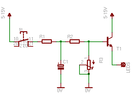
To make it more easy, i will break the circuit in two parts. The first part will be the controller, which is exactly the same no matter what power supply is used. The other part is the LEDs. I will show you some different configurations for different voltages and LED numbers. So, here is the controller:
The R1 protects the capacitor from over-current shock, when the pushbutton is pressed. R2 and R3 will determine the time that the transistor will supply current to the LEDs, as they actually determine the discharge of the capacitor. You should be very careful with the connector "LEDS", because the transistor is NOT protected from over-current. If this connector is grounded for any reason without a limiting resistor, then the transistor will wave bye bye immediately. The LEDs are connected to this connector. According to the power supply and the LEDs that you want to light, you should choose the connection from the bellow suggestions. Note that these schematics applies to LEDs with operation current 30 mA and voltage drop 3.6 Volts! In case you have different LEDs, you need to calculate the protective resistor yourself (go to the LED Resistor Calculator)
To adjust the off-delay time, play with the R3 potentiometer. Higher resistance means more time to turn the LEDs off. You can further increase the off-delay time, by changing the C1 capacitor. You can use for example a 220uF or a 470 uF, or bigger. The more the capacitance, the more the off-delay. Just keep in mind that if you plan to use the circuit at 15Volts power supply, do not use a 16V capacitor. Use a 25Volts or bigger.
Moreover, if you plan to push the circuit to the limits, I suggest that you measure one row of LEDs to see how much current flows, and check if this is the same (or very close) value as i have measure in my circuit. This is because there may be big differences due to the different LEDs that you may use.
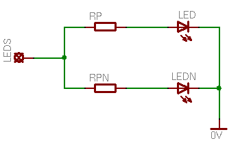
5 Volts power supply
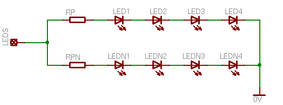
To save space, in every schematic that will follow, i will mark the first row with the letter RP for the protective resistor and LED (LED1, LED2...) for the LEDs. This row can be multiplied a number of times, according to the current that is drawn. I will mark the 2nd row with RPN for the protective resistor and LEDN (LEDN1, LEDN2...) for the LEDs, but this line can be multiplied more times.
When powering with 5 volts, only one LED can exist in each row, as each LED drops 3.6 volts. The protective resistor for each row must be 47 Ohms. Each row draws about 24mA. The 2N2222 can handle up to 800 mA IC. So, with 5V power supply you can control up to 33 rows of LEDs, which means that you can control up to 33 LEDs.
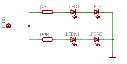
9 Volts power supply
With 9V power supply, each row can have 2 LEDs. The limiting resistor for each row is 68 Ohms, and a current of 24 mA is drawn. This means that the transistor can supply 33 lines of LEDs. So with 9V power supply, the circuit can control up to 66 LEDs.
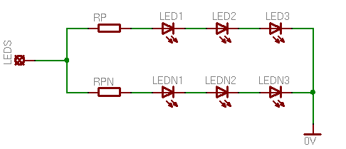
12 Volts power supply
With 12V power supply (or 13.4 from the car), each row can have 3 LEDs. The limiting resistor for each row is 47 Ohms, and a current of 30 mA is drawn. This means that the transistor can supply 26 lines of LEDs. So with 12V power supply, the circuit can control 78 LEDs.
15 Volts power supply
With 15V power supply, each row can have 4 LEDs. The limiting resistor for each row is 20 Ohms, and a current of 30 mA is drawn. This means that the transistor can supply 26 lines of LEDs. So with 15V power supply, the circuit can control 104 LEDs.
At 13 September 2015, 19:28:06 user naveen wrote: [reply @ naveen]
I have 4 3v led connected via a resistance to make it operate in 12v.
Totally 9 sets in parallel consuming 12v 1 watt power supply.
If i want to make this dimming effect in my circuit, what capacitance i have to use and also please explain which transistor to be used?
Note: I am using car battery.
@Giorgos Lazaridis I've worked up a circuit using this fader where the switch(S1) is replaced by a MOSFET (which is controlled by a 555 timer), and more importantly where the voltage is 3.3V. Can you tell me if the fading will still act as it does in this circuit with the listed Bill of Materials if all sources are 3.3V?
Hello we would like to make this circuit have a time period of 20mins if possible for a design and technology product. Is that possible or would we be looking at resistances on the resistors that are just far too high for the circuit.
Hi, am trying recreate this circuit but no fading. I push the button and it runs on and that it. am not using a 2n2222 but a 2n3904 could that be the problem?
@martin sennett Analog circuits are awesome because they rarely fail, but they are hard to design. A microcontroller would solve your problem... I think you need to consider using one soon.
Hi Giorgos, you are right. My current thought is a 555 set up as a ramp generator (easy to make), driving the minus input of a comparator. As I move the positive input of the comparator up/down it will vary the mark/space ratio of the square wave output of the comparator. The problem will be automating the positive input. The ramp up/down times are massively too long use the charging of a capacitor. I could try use a 555 driving a counter (a diode on each counter output, cathodes all coupled to the same capacitor {in parallel with a bleed resistor} to provide a ramp voltage. Might be worth breadboarding. If you have any thoughts, they would be appreciated. If it works, then it is just a little extra circuitry (timers and logic) and a couple of pots, so that (at switch on) the LED's brighten over a time I can set/change, and remain at max illumination for a period I can set/change, dim at the same rate as they brightened, AND then stay off (I would switch off power before going to bed. There is probably an elegant and simple way of doing this with a microcontroller, but I have never played with those. Best wishes Giorgos, Martin
@Martin Sennett You need a much more sophisticated circuit than this. This one cannot help you
At 20 February 2013, 5:04:49 user Chris wrote: [reply @ Chris]
Howdy!
I wanted to run a 5 volt or smaller LED. When I pressed a button, the led slowly fades on, holds for a few seconds longer and then fades out slowly. Perhaps like 30 seconds hold at full brightness.
Are there any kits for this? It's for a Terminator eyeball ;) powering up and powering down.
Hi Giorgos. I have 2 tropical fish tanks (24L & 180L). I am waiting for a 2W 28 LED array to arrive for the 24L tank. I would like to be able to build a circuit that will let me make the LEDs work as daylight does - the LEDs start dim and reach full brightness in about an hour, they stay at full brightness for 10 hours or so, then dim out over an hour. Saw your 555 circuit and your delay circuit. I trained in electronics (in the 60s), but have not practiced for probably 25/30 years. I can think of solutions, but they are messy. If you have ideas, let me know - if I get them working on the small tank, then I will apply them to the other tank (70W of aquarium fluorescents - they run hot - mean I have trouble keping the temperature where I want it). Cheers, Martin
@Alan it is the transistor and the base bias current of the transistor. You need a second transistor to drive that much current. Check out here:
http://www.pcbheaven.com/circuitpages/LED_Fade_In_Fade_Out_Dimmer/
Section Need more current?
At 23 January 2013, 18:26:13 user Alan wrote: [reply @ Alan]
Hi, I'm making a circuit up for strip LED lights. Because I'm new to all this I just made this circuit up as described above. It's become apparent that the output voltage is not enough to power 4x 30cm strips (when switched on, the light output is at about 60%). Each strip is about 120 MA and I'm running 4 strips off this circuit. So, just wondering what I need to change. I imagine it's transistor issue not delivering required power? Also if I bypass R2 then I get full brightness but the fade out time is too short (about 1.5 seconds). Any thoughts? Thanks.
At 11 December 2012, 8:33:56 user Ilya wrote: [reply @ Ilya]
@Giorgos Lazaridis I was right, just tested it. If I put my LED strip between positive terminal and collector everything works like a charm.
At 11 December 2012, 4:31:12 user Ilya wrote: [reply @ Ilya]
@Giorgos Lazaridis I guess I got it. I have to put my LED strip between pos. terminal and collector not between emitter and ground.
At 11 December 2012, 3:51:35 user Ilya wrote: [reply @ Ilya]
@Giorgos Lazaridis here's a what I have (omitting capacitor and pot), you can run simulation to see what I was talking about
At 11 December 2012, 3:23:43 user Ilya wrote: [reply @ Ilya]
@Giorgos Lazaridis Doesn't help. I've tried replacing transistor. It's all the same. As I'm using 12V power supply I should get approx 12V at emitter? Is it correct?
@Ilya strange... remove the transistor and measure again.maybe it is dead
At 10 December 2012, 13:20:32 user Ilya wrote: [reply @ Ilya]
@Giorgos Lazaridis Hmmm....doesn't help. Just tried it today. No change at all. I guess I understand smth wrong. I use 12V from car battery, so at the base of the transistor I get 5.5V, at the emitter I can read 5V what makes sense, but how do I get 10-12V at the emitter? My LED strip needs 12V to operate.
@Ilya you need a second transistor because the first one has a big resistor in its base. So, although it can provide voltage, it cannot provide enough current. You can use a second 2N2222 as well. Each transistor will drop about 0.7 volts, so for 12volts you need more than 13.4 volts (for 100% brightness). To see how to connect the transistor check this page:
http://www.pcbheaven.com/circuitpages/LED_Fade_In_Fade_Out_Dimmer/
Read topic "Need more current?"
At 9 December 2012, 16:29:16 user Ilya wrote: [reply @ Ilya]
@Giorgos Lazaridis I'm using 2n2222 transistor, afaik it's can hold up to at least 500mA. Why would I need a power transistor? I'm new to this. Been reading a lot about BJTs lately, still don't understand some things. One more thing when I connect my LED strip, the voltage at emitter drops to about 5.5V, why?
@Ilya you need more current, so you need a extra power transistor at the output for more current
At 9 December 2012, 8:38:39 user Ilya wrote: [reply @ Ilya]
Trying to implement the circuit above. It works just fine with one led. But as soon as I connect my led strip, it doesn't work. LEDs glow very dim. I can't say much about leds used, it's a generic led strip bought off Ebay. It has series of 3 leds with 332 Ohm resistors. It's an old one, so leds are not super bright. When connected directly to a battery it draws approx. 100mA. Any hints?
I needhelp. I want to build this circuit but dont see the need for the potentiometer. I want it to run off 9 volt battery. And operate like the video. I know nothing about electronics but could use the help. I want to incorporate a LDR CIRCUIT that when its dark runs to a vibration switch, then when the switch is activated it turns on 2 led lights for ten to fifteen secinds then off till the switch is activated again. Please someone help?
@Silda aha! now i understand what you mean. Do you want to make off-delay for your car? Because usually cars have pull-down switches. Anyway, if this is the case, this circuit won't work. You need an arrangement like this:
http://www.pcbheaven.com/circuitpages/Car_Dome_Light_Off_Delay/
But that won't work very effectively for LEDs. I've told to some readers that i will make one car dome light off-delay with LEDs, but that won't happen right now. Maybe it will be my next circuit, i am not sure for time is limited for me this period.
Anyway, if car dome is not your project, then you may need to change the transistor to a PNP and reverse everything on the circuit - potentiometer and cap goes to , collector goes to -, LEDs are connected between and emitter.
@Giorgos Lazaridis yes, i understand, what i'm trying to do is move the S1 to the negative side, so the R1 will directly connected to 12v and to R2 in the other side. I need the Switch to be at the 0V rather than the 12V, i just don't know where to put it, or if it even possible.
Hi Giorgos!
The swicth of this circuit is on the positive side, is there any way to make the switch at the negative ( the ground ) side? I have tried to put switch before Capasitor and the potensiometer ( ground side ), it's dimming but the delay time is way to fast, where i should put more resistor? Thankyou.
geez... read this : http://pcbheaven.com/circuitpages/Car_Dome_Light_Off_Delay/ after post a comment here, i think i found the answer there. Thankyou.
Anyway you can use BC547 transistor if you can found 2N2222. Thank's again!
Hi!
I made it!. One question, this circuit work as it should be if the Transistor's (T1) Collector pin stay connected to power source after switch off, if the collector pin power cutted also, it won't dimming, LEDs immediately off. Any tricks to avoid this? Let's say i want to make a cabin lamp dimmer for my old car, the power controlled only by door opening/closing, no other switch involved. Thank you.
@Charlé hello, i use typical 1/2 watt potentiometer. As for the transistor, since this is a simple emitter follower, any NPN with sufficient Ic will work.
Hi, what wattage pot are you using? I just tried the circuit with a really small wattage preset...I wouldn't recommend this. Also would you be able to recommend alternatives to the 2n2222 transistor? Thanks.
At 3 April 2012, 7:33:06 user lito wrote: [reply @ lito]
@Giorgos Lazaridis
I'm not really sure how much are the total current and voltage of this module but its already with resistor so i put 4module in parallel then connect to my motorcycle(12V battery)
i will try to buy all the parts(above) and try to connect to this 4 module but i will try to use the 2N2222 Transistor
At 3 April 2012, 5:37:20 user lito wrote: [reply @ lito]
@Giorgos Lazaridis
thank you very much for the explanation
i also have another question
do i need the BD243 if i will try to used this led module?
i will use 4 module that will connected to motorcycle battery 12V-13.5V
http://image.made-in-china.com/2f1j00aBetuqCcsEhD/3LED-Module.jpg
@lito if you need to increase the current it is better if you add a second transistor to the circuit rather than just replacing the 2N2222. That is because there is this R2 which limits the base current.
So you may wanna use this connection:
http://www.pcbheaven.com/circuitpages/LED_Fade_In_Fade_Out_Dimmer/
At the bottom there is the "Need more current?" title.
Remember thought that each transistor you add will drop the output voltage by 0.7 volts. So, adding 2 transistors at 12V supply will result in maximum 10.6 output.
At 3 April 2012, 4:39:46 user lito wrote: [reply @ lito]
@Kammenos regarding the need more current question of Kammenos all we need to change is only the T1 from 2N2222 to BD243?is this correct?no other device will be change?
At 12 February 2012, 17:12:28 user Rob wrote: [reply @ Rob]
Thanks a ton! I'm just a beginner, but needed a timing circuit like this to shut off some flashing led circuits that needed to be light weight (ie no relays) for a pinewood derby car.
@sharaz you don't need an image, let me explain: the pot has 3 pins: we will call them LEFT MID and RIGHT pins. The LEFT pin is connected to the R2 and the transistor. The MID and RIGHT pins are connected together to the 0 volts. If you need more explanation please open a thread in the forum. Here we cannot upload images.
At 18 December 2011, 16:20:50 user sharaz wrote: [reply @ sharaz]
hello sir,
might be my question is very basic as i am not familiar with most of the electronics. can you please explain the potentiometer a bit more how you have connected it with the circut. as i am getting problem when i attach potentiometer the led light get dimm and the capistor also discharge very soon. i am using the circut without potentiometer, i need the result as you have shown in youtube video.
can you please upload the picture of your potentiometer and how you have connected it, please,
There seems to be a write-up error with the last 2 samples (12v & 15v).
"So with 9V power supply, the circuit can control 104 LEDs."
"So with 9V power supply, the circuit can control 78 LEDs."
Shouldn't this be 12v & 15 respectively?
Nevermind the answer. I see it is not critical but, relative the values. I used what I had a 100 Ohm R1 and a Pot of 100Kfor R3. The circuit works. Brilliant. Now, I just do the math and play with the t=RC values to vary the time. If r3 is 0 ohms then the capacitor discharges through the light too fast to see. As I raise the resistance through R3 the light stays on longer. If higher capacitance the light also stays on longer. FUN. Thank You!
@Rick i'm very sorry but due to lack of time, i cannot do that. I try to administer the whole site by myself and myself only.
At 3 October 2011, 7:38:20 user Rick wrote: [reply @ Rick]
Thanks, I read that after I posted the comment. I see you have one on another page about the dome light. I'm still curious to know how to read the circuit. I'm having trouble understanding how to wire everything together. I'm not reall familiar with electronics. I was wondering if you could do a how to on the done light? From start to end showing all the solder points. If you could that would be greatly appreciated.
@Rick this circuit is actually not proper to use for car dome light because usually, the car's on-off signal comes from earth and not from positive. It is for educational reasons mainly.
At 28 September 2011, 23:47:35 user Rick wrote: [reply @ Rick]
I came across your video on you tube and would like to make this for the dome light in my car. I have never messed with electronics like this before. I kinda understand what needs to be done but I'm having trouble reading the diagram. I don't know what the different symbols and stuff mean. I am asking if you could be explain and maybe make a vedio of you assembling this. I plan on using a project box from radio shack and a curcuit board to soder everything to. Thanks.
@Rollie you do not solder on the breadboard. if you want to solder use perforated prototyping PCBs
At 21 September 2011, 12:53:10 user Rollie wrote: [reply @ Rollie]
Your Video was very interesting specially to those who are new to the electronic world like me. could you please show to us how did you connect each materials on the breadboard by soldering. I\'m planning to put also into my car. thanks
@RAIN i do not recommend to use this circuit for dome light, because dome lights usually use negative to trigger. If your car use positive, then connect the positive to the input of R1
At 20 August 2011, 8:48:05 user RAIN wrote: [reply @ RAIN]
if i will use it in a car dome light hows the connection? im really interested to this proj. i hope you could help me especially in wiring to my existing dome light, thanks
hi!!!
i have been seeing your videos and u explain them very well. It is giving me a great amount of practical knowledge. Basically i am an electronics engineer.
thank you
@Mark It has to do with the current that your strip will draw. Normally, it should work, but if the current gets high, then the transistor will not be able to deliver enough current. You then may consider using a power darlington pair transistor instead as a second stage.
Regarding the button, no, you can only use an on-off switch.
At 28 July 2011, 13:39:58 user Mark wrote: [reply @ Mark]
Just wondering if this would work with a row of strip LEDS like these: http://www.ebay.com.au/itm/12V-5M-300-LED-3528-SMD-White-Flexible-Light-Strip-car-/220745713088?pt=AU_Car_Parts_Accessories&hash=item33657845c0
if so, would i need to make any modifications, and could i use a momentary switch, or will i need an on off type??
But there shouldn't really be any risk of this happening since there's no reason the emitter would be connected directly to ground, am I right? Or do you mean the ground from the leds?
Perhaps what you're saying is that there needs to be a resistance to the collector if I use a power supply with more Volts than the collector can handle? If so, it would make sense to me.
oh, i mean the connector for the LEDs, which is the emitter of the transistor. If there is no limiting resistor to the collector or the emitter, and the emitter (LEDS connector) is grounded directly, then the transistor will die immediately.
Yes Devinz, you can use a transistor to invert your signal.
At 15 February 2011, 11:17:11 user Devinz wrote: [reply @ Devinz]
I'm thinking can I still keep your circuit but I just convert my negative signal to positive by a transistor.
Is this make sense?
With a transistor, my original negative signal go to the transistor 'base' and the positive for collector and the emitter as the 'S1'.
* The EBC terminals might be wrong from above as I\'m just an amateur..
Devinz, you need to make the symmetric circuit with a PNP transistor. For example, replace 2n2222 with 2n2907, C1 and R3 should be hooked to positive, emitter of T1 goes to positive and you get output of the collector. Roughly this is the idea, but i have not test it. It may not work at once and you may need to run some extra experiments. If you test it and it works, please be kind and tell us the results.
At 15 February 2011, 3:03:35 user Devinz wrote: [reply @ Devinz]
If I can only use the negative signal to turn on the circuit, how can I convert my negative signal to positive signal for this circuit (for the S1).
I know how to do it by a relay but how can I do it with a transistor?
Thx.
Hello Sebastien,
I am not sure, but you can try this by adding a big potentiometer (like 500K) in between R1 and the pushbutton (S1). Do try it and tell us the results.
Is it possible to add an ON Delay with dimming effect too on the same circuit ? I mean, when the pushbutton is pressed, it will have an ON Delay with dimming effect and when you release the button, the OFF Delay with dimming effect will be.

 Home
Home
 Projects
 Experiments
 Circuits
 Theory
 BLOG
BLOG
 PIC Tutorials
 Time for Science

 Contact
 Forum
Forum
 RSS
RSS


 Reddit this

