The circuit on a breadboard for test. I use 5 volts for power supply
A few days ago, someone posted a question to the forum about dimming LEDs. He had a schematic with a potentiometer that would control a batch of LEDs. I then suggested that he would better use a PWM circuit to control them. And guess what... I did not have one! So, here it is:
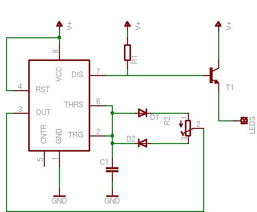
The Circuit
The circuit is based on the 555 timer, connected as a PWM generator. Again i will use as output the discharging capacitor from pin 7, which will control the base of the power transistor. Similar to the LED Off Delay with dimming effect circuit, i will break the circuit into 2 pieces, the controller and the LEDs. The circuit can operate at a wide operation voltage, from 4 to 15 volts, and the only thing that changes is the LED array. Here is the controller circuit, able to operate from 4 to 15 volts as is:
The potentiometer R2 controls the charge and discharge times, and thus the duty cycle of the PWM. In other words, the R2 controls the brightness of the LEDs. R1 pulls up the discharging transistor (inside the 555). The LEDs are connected to the "LEDS" pad on the right.
The LEDs
I will suggest some connections that i have already tried and took some measurements myself. For these connections, i used high brightness 30 mA 3.6 Volts 3mm and 5mm LEDs. You can use whichever LED or connection you like, as long as you do not exceed the current limit of the transistor (for the 2N2222 this is 800mA). As always, click to enlarge if an image is too small.
Power supply: 5 volts RP = 47 Ohms Max num of rows: 33 Max num of LEDs: 33
Power supply: 9 volts RP = 68 Ohms Max num of rows: 33 Max num of LEDs: 66
Power supply: 12 (13.5) volts RP = 47 Ohms Max num of rows: 26 Max num of LEDs: 78
Power supply: 15 volts RP = 20 Ohms Max num of rows: 26 Max num of LEDs: 104
For each LED connection above, i give some characteristics. First of all, the power supply. This is the power supply that the controller operates with. As i told you before, only the LED array will change with the power supply.
Then the RP. The RP is the protective resistor for each row. Each LED row must have its own protective resistor. Although multiple LEDs connected in parallel can use just one resistor, this must be avoided. LEDs should always be connected in series with resistors. Each row composed by a number of LEDs and a protective resistor (RP) can be multiplied in parallel, as many times as the 2N2222 permits.
The next number shows exactly this: the number of rows for each connection that the 2N2222 can handle. For example, when powering with 12 volts, the transistor is capable to drive up to 26 lines of 3 LEDs each (and of course a protective resistor on each line) and that is the current limit of the 2N2222. If you think of pushing the transistor to the edges, then you should first measure the real current that your LED array draws, and do not exceed the maximum 800mA that the transistor can handle. Remember that the transistor may need heat-sink if it gets hot.
The last number, indicates how many LEDs in total can be controlled with each connection. For example, when powering with 15 volts, the transistor can control up to 26 rows of 4 LEDs each, that makes 26 x 4 = 104 LEDs in total.
Thank you very much for this circuit
We used it for lot of led strip. We changed transistor with mosfet IRFP140n and built 2pcs with 4 channel to control each channel 14 peaces o 3m long tape.
Working well so far. Tape was 24V so we put one additional 12V adapter for the oscillator. One ic can control well up to 4 Mosfets in paralel.
Hey there!
I would like to use that circuit to control the LED like this:
http://www.amazon.de/Salcar%C2%AE-SMD5050-IR-Fernbedienung-Controller-Netzteil/dp/B00ABW3X92/ref=sr_1_6/280-8662932-1114505?ie=UTF8&qid=1436530599&sr=8-6&keywords=lichterschlauch led au%C3%9Fen
That is, SMD5050 LED's.
I would estimate that the LED-tube has a length of roughly 4m. That would make about 100 to 120 RGB-LED's (so 300 to 360 LED's).
I plan to use one of the circuits above for each colour.
I have a 12V 2A - Power supply, but would maybe upgrade to higher Ampere.
What would I have to change in the above circuit? Only the transistor??
Any chance you can comment on the difference between your circuit here, and this one: http://cdn.instructables.com/FGN/8X56/GBF5KOQQ/FGN8X56GBF5KOQQ.MEDIUM.gif
I'm just trying to understand, and that one I found before yours. They use the same parts, more or less, but theirs has pin 3 outputting to the LED and yours uses pin 7.
I also want to know if there is any benefit of using a constant current driver IC on the output side before the LED rather than directly connecting output to the LED?
@Roel I'd say first remove the LDO and replace it with a resistor. Go to the following page to see how to do the calculations for the resistor:
http://www.pcbheaven.com/userpages/LED_driving_and_controlling_methods/
Let the whole circuit operate at 9V and put a resistor (calculated above) in series with each led. Note also that the 555 needs at least 4V to operate normally.
At 3 January 2015, 17:03:16 user Roel wrote: [reply @ Roel]
@Giorgos I've got the appropriate powersupply, everything works like it is supposed to do now. Still need to do the housing for it, I'll post the result when it's done.
I've used this circuit for another project, a stage design (miniature) my girlfriend is working on for uni. The LED's dimm down to about 25% but no further (3.3v SMD LEDs, 1 per circuit). The only thing I've changed is the input voltage, I've used a 3.3v LDO regulator connected to a 9v battery. Any pointers?
At 16 August 2014, 22:01:50 user iux wrote: [reply @ iux]
Great tutorial. Others have asked about increased leds/amps and you offer other suggestions mosfets etc.. however, after looking at IRFL014, its power-max is 1w/2w (unless I am reading it wrong)
http://www.digikey.com/product-search/en?k=IRFL014&mnonly=0&newproducts=0&ColumnSort=0&page=1&stock=1&pbfree=0&rohs=0&quantity=20&ptm=0&fid=0&pageSize=25
Would this part work for running 12v pulling 1.2 amp?
Hi, I am interested and very enthusiastic about your project (PWM LED DIMMER), I am an electronic enthusiast and a hobbyist., can you please send me a BLOCK DIAGRAM and also the components needed ? I will make 1 for my litle room.
Hoping for a positive reply and Thanks A Lot
June Ramas / Philippines
At 14 January 2014, 21:03:52 user Roel wrote: [reply @ Roel]
@Giorgos Yeah I was using a led specific SMPS. I didn't know about the switching part until I went trough the internals though... A linear power supply would solve the problem, but they are quite big, expensive and not that efficient (i've been told). Are there any other options? Using a different power source with a regulator or something like that? I'll start looking for something linear in the mean time.
@Roel I'd suggest you go with a linear power supply. I suppose you use an SMPS???
At 12 January 2014, 16:55:21 user Roel wrote: [reply @ Roel]
@Giorgos I'm still working on the desk lamp, just soldered all the parts to a test pcb and it's working fine.
I'm having quite a problem finding a suitable power supply though. The one I bought for it causes flikkering in the LEDs, probably due to the PWM frequency. I've tried using capacitors as filters, it worked but not efficiently (large high capacity CAPs only seemed to do the trick). Do you have any suggestions? I'm powering the above setup but with a MOSfet and 3 * 3W powerleds. On a 9v battery it works like a charm.
At 21 December 2013, 18:17:30 user igor wrote: [reply @ igor]
all made %u200B%u200Bby the scheme, but does not work if anyone can help please write to my mail
shadal490@gmail.com
I want to dim a complete strip of around 300led's which is powered by a 12v 2 amp power supply. Its too bright i want to dim it. What components do i need to change?
@Pete Most likely they have different hFE. Typical for transistors. You'll need to take measurements and decide which R1 to use
At 30 August 2013, 14:36:39 user Roel wrote: [reply @ Roel]
@Giorgos Fixed it! I've made a mistake wiring up the Mosfet to the timer, now everything is working like a charm! I hope I've got some time the next couple of weeks to finish the lamp design. i'll post some pics when it's done.
At 23 August 2013, 16:14:25 user Roel wrote: [reply @ Roel]
@Giorgos I had to order some new resistors, so it took me a little longer to try it out!
The result is pretty much the same. I've tried some other resistor values, but it didn't really make a difference either. Do you have any suggestions?
This circuit works pretty well.Now I'm trying to use a digital potentiometer(X9C103P) instead of the R2 in the circuit so that I can control the dimming with a micro controller. When I power up the cct with a digital potentiometer, Voltage across the LEDs drops only to half of what is supplied.
For example, If 3 LEDs are used with 12V supply, voltage across the LEDs is around 6V at the maximum level of dimming.
Please provide me a solution.
Thanks in advance
@Roel If you use a mosfet, R1 has to be small, but not too small to violate pin 7 max current sink. use ohm's law to calculate: R= U/I where V is the supply voltage and I is the max allowable current sink of pin 7 (check datasheet).
But since you use mosfet and the gate ecurrent is practically 0, do this: Add a resistor between pin 3 and the potentiometer (say 220 Ohms) and then connect the gate of the mosfet to pin 3 through a 100 Ohm resistor. Remove R1 and leave Pin 7 unconnected. Try this setup and post us the results!
At 14 August 2013, 8:40:28 user Roel wrote: [reply @ Roel]
@Giorgos Lazaridis I received all the needed parts yesterday and put it all together in a test setup last night (couldn't wait). The Mosfet solution works flawlessly, thank you for that. I've got one issue though, the dimming goes from 100% to about 30% and not entirely to 0%. In one of your replies you mentioned this could possibly be an issue with the R1 (the potentiometer is working fine), can I someway calculate with what type of resistor I need to replace it with?
At 6 August 2013, 13:01:50 user mick wrote: [reply @ mick]
Is someone producing a pcb for this circuit that is available for purchase.
I have seen a jpg of a pcb for this dimming cuicuit but can't trace it down...here is a link....jpg is on the far left of the page.
Any help in finding these pcb would be appreciated.
regards,
Mick
At 6 August 2013, 11:00:59 user Pete wrote: [reply @ Pete]
@Giorgos
Ok.. now i am really confused and i am hoping you can help an electrical noob out!
So i took out the transistor and used pin 7 of the 555 to sink the current of the LEDs and it worked perfectly, beautiful dimming! So the problem is in the transistor. However testing and replacing the transistor tells me its not dead so....
The only other difference i notice is that I am using an MPS2222A transistor instead of a 2N2222. The datasheets say the are pretty close, but there is obviously a difference i don't understand.
Can you explain to me why this transistor wouldn't work??
Ta
Pete
At 2 August 2013, 13:40:36 user Pete wrote: [reply @ Pete]
@Giorgos
Tried 3 pots, all measure linearly across the range. both diodes measure good, even tried swapping 555's and cap's just to be sure! Always the same behavior.
I only notice that my Rp is about 4 or 5 times larger than what you suggest for a 5V circuit, could this impact?
I guess the only way to know for sure is to put a scope on it... may have to buy the guys at work some beer and borrow their lab!
At 2 August 2013, 10:17:52 user Roel wrote: [reply @ Roel]
@Giorgos Ok great, I'll go and order the required parts. I'll let you know how it turned out.
@Roel A N-channel mosfet is ok or your application. Since the current and the voltage are both low, almost all N-channel mosfets will do. The LED anode goes to V , the cathode goes to the mosfet Drain, the mosfet Source goes to the gnd. Its a typical low side switch.
At 2 August 2013, 10:04:22 user Roel wrote: [reply @ Roel]
@Giorgos I've never worked with mosfet's before, but I would like to give it a try. I've done some reading/research myself, but I find it hard to pick the right type of mosfet for my project. Can you recommend one?
At 26 July 2013, 14:08:03 user Pete wrote: [reply @ Pete]
Hi Giorgos!
I have made this circuit and am having some strange behaviour from it. As i dim the circuit down from 100% the LEDs dim a little bit but not too much. At around 30% they suddenly turn off. Then below about 20% they turn back on!
Any idea whats gone wrong?
I am running 3mm high brightness leds with 180ohm Rp (built in) on a 5V supply. I plan to run 10 leds but the behaviour is the same with any number.
@Mick. Maybe smaller R1? Be careful the max current allowed through pin 7 (i think it is 35mA).
If you have an oscilloscope, make sure that the output goes all the way from 1% up to 99% duty cycle. If not, then there is something going wrong with the 2 diodes.
Hi..I've assembled the dimmer as per your instructions...thank you :) ,
however I only get a limited ammount of dimming...when I turn the 10 k trimpot it dims to full brightnes in less than quater turn and doesnt dimm all the way to nothing it only dimms to half brightness.
I'm using a mosfet and 84 x 10 mm leds in parallel at 3.6 volts.
Is there something i can alter or modify to get full control.
Cheers Mick.
At 19 July 2013, 11:42:04 user Roel wrote: [reply @ Roel]
Thank you for this great tutorial, this circuit is way more efficient then the one I had in mind.
I'm going to use it as a base for a new desk lamp I'm working on. The 3 leds I'm going to use are 3.3v 700ma (160 lumen each) and a 12v 2a power supply and I'm going to replace the 2n2222 with a transistor that can handle the higher load. Is there anything else I need to keep in mind except swapping the transistor?
At 25 June 2013, 13:31:04 user John wrote: [reply @ John]
Hello, I want to build an array of 5 red LEDs (5mm) that I can dim to faintly light up an area. I found your project, and the dimmer circuit in '50 555 circuits' that can be found thru google (search for 'dimmer' in the file). Theirs doesn't use the 2N2222 transistor. Is there any advantage to your project over the one I mention?
At 22 June 2013, 4:31:21 user qao wrote: [reply @ qao]
is it possible to control this with 0-5V output of a d/a converter instead of the R2 pot? if so, how would you modify the circuit? Thanks.
@mark 15Watts flashlight? WOW! You need to connect 4 batteries in series to get 14.8V, then a buck regulator or other sort of linear regulator (i do not recommend linear regulator at 1.25 amps) to drop down to 11.7V
I dont have circuit design knowledge but i could follow a diagram with parts numbers. Id like to make a led driver using a slide dimmer switch with on and off for my personal flashlight. The led data sheet im thinking of using says 11.7 volt 1.25 amp. I have 3.7 volt rechargeable 18650 batteries to work with. Could i get a diagram with an efficient solution for my problem? I walk and bike at night but am afraid i will get hit by a car because i hate and wont buy one of those clicky flashing mode flashlights currently found for sale. I appreciate your teaching and attention.
@George The problem is EMI. Make C1 a little bis smaller or make R2 smaller. this will increase the PWM frequency above audible spectrum. But you will not be able to 100% remove EMI unless you shield the cables and all the high frequency potions of the circuit near your audio cables
@jester lopez I'm sorry but i cannot make circuits on demand. Not enough time.
At 25 February 2013, 18:06:59 user George wrote: [reply @ George]
Excellent job at explaining in detail the theory and value calculations in all of your tutorials.
My problem is trying to remove the high frquency noise that is associated with PWM 555 circuits.
I want to be able to dim 8 LED's (one is bi-color) mounted in the same metal enclosure and using the same 9V DC power I built to rout audible signals, in this case switchable musical instrument effects signals (guitars mostly). Your circuit works great for the dimmer but I cannot have the High frequency noise which is really noticeable when the instrument output is connected to a guitar amp.
I have tried adding small caps the smallest being 100pF to pin5 & gnd.
Adding caps to the emitter to gnd thinking LED noise.
Adding caps across main power & gnd.
If I remember correctly High frequencey noise filtering usually means lower cap values.
I have also tried using a TLC555 which did lower the noise but it's still there.
I have not tried a 7555. Not sure if that would eliminate noise completely.
NOTE: As I move your circuit design closer to the instrument output jacks the noise is louder. Even if I just move the potentiometer towards the output.
Thanks for any suggestions.
This is driving me crazy
George
@karim ahmad Oh i see. no this one will not work for you. you need a circuit like this:
http://www.pcbheaven.com/circuitpages/Ambient_light_Level_Equalizer/
Hi, I did something similar, I conect use the pin 3 instead the 7 and conected a more power transistor (TIP31NPN) and it works very well. I follow some indications from this web:
http://www.reuk.co.uk/LED-Dimmer-Circuit.htm
Thank you for your response!
Cheers
Juan
@Juan Matte Hello and sorry for the totally delayed answer - i missed this comment and saw it only when another arrived at this page.
The problem you mention is typical for high current applications using transistors. The 2N2222 has an hfe of around 40. With base resistor 4.7K, it cannot deliver current higher as I= 12/4700 x 40 = 102mA
So, there is a very elegant solution to your problem, and that will be a mosfet. Mosfets are generally irrelevant to base resistors in terms of current supply. So you wanna change the transistor T1 as shown in this circuit:
http://www.pcbheaven.com/circuitpages/High_Frequency_PWM_Fan_Controller/
In the middle of this page i show a PWM circuit with an IRF520 mosfet (Q1). You are free to use smaller and cheaper mosfets as the 520 can handle up to 9A and costs a little bit high.
Hi Giorgos,
Thank you very much for your post and the circuit it is very simple so thanks again. But I have a problem with that; I am working in plant science so I had to build an array of blue, red and far red LED. I have 1W LED, all of them Vf 350mA and the Vf of the blue is 3.3, Red is 2.2 and the far red is 1.8. I am using 12V of power source and I put in serial 3 blue LED with a 4.7 ohms resistor, and when I connect them directly to the 12 Volts I got full bright (I guess is 3W), but when I use the circuit I got half of the intensity at the maximum level. I measure with my tester the voltage in 1 LED and when is connected directly I got 3.3V but through the dimmer I only get 2V%u2026 I don%u2019t understand what happen that using the dimmer the voltage decay to the half, and the only think that is between the 12V and my LEDs is the transistor. I upload a video in youtube if you want to have more details.
I will really appreciate your help because you will understand much better what is going on with that, I only have a basic knowledge in electronics, enough to connect LEDs and understand that the transistor is a switch controlled by the 555 timer, then I don%u2019t figure it out why I had lower voltage and also I was expecting constant voltage but then I don%u2019t know again if he tester is not a good instrument to measure that.
Thank you very much
Juan
http://youtu.be/9K7DBz7MIqg
At 8 October 2012, 18:11:49 user Juli wrote: [reply @ Juli]
@Giorgos Lazaridis not with this circuit. You need a PWM generator controlled by a DC voltage. You supply the line out (using of course a transistor or other sort of impedance matching) to the input of the circuit. here is a more complex circuit but may work for you with little modifications:
http://www.pcbheaven.com/circuitpages/Voltage_Controlled_PWM_Generator
This is a great and neat circuit. I've been looking for something like this for almost a week. My question is: Is there any way to connect an audio line -to/or replace- the potentiometer to control the brightness of the leds through sound?. I plan to replace the transistor so it can handle a 1 watt ir led.
@dvnmk you will need 3 555 timers, one for each channel. also, there is no flickering, the fader is not pwm, it is linear
At 9 September 2012, 15:11:01 user dvnmk wrote: [reply @ dvnmk]
Great article!
If I have several diffrent led colours that I want to dim separately do I need separate circuits for each or can I use the same 555 somehow?
I also have some worries about flickering, is there a way to delay the signal for some LEDs so that the light pulses are more evenly distributed in time?
@Melvin you will need to add either 2 transistors (one to amplify the base current of the power transistor), or get the output of pin 3 instead and not pin 7. That is because the transistor you propose has hfe 20, so needs some 50 mA at least to drive 1000mA. Pin 7 can sink up to 25-30 mA, while pin 3 can source much more. I suggest you use pin 3 with a limiting base resistor of about 180 Ohms. As for the LED resistor, better connect the transistor as a current source:
http://www.pcbheaven.com/userpages/LED_driving_and_controlling_methods
At 5 September 2012, 19:04:51 user Melvin wrote: [reply @ Melvin]
I think this will be perfect for my dimmable 12v car battery floodlight plans. Would the 2n3055 transistor work? The led will be a 3*3 ledpanel wich needs 9-11V @ 1A, you think I can just use a current resistor to control the current? At what frequency do the leds flash? Thanks!
@Don if the voltage does not exceed the 15 volts, then it is ok to do this.
At 26 July 2012, 17:55:06 user Don wrote: [reply @ Don]
That's fine. Thanks anyways!
Do you know if I could say buy a 12V AC adapter from something else (like a game system), strip the wires and solder it to this circuit? Would that work?
@Don yes it requires a whole other circuit, a power supply. i cannot provide this circuit though.
At 25 July 2012, 21:30:24 user Don wrote: [reply @ Don]
This circuit is exactly what I've been searching for! Thanks so much!!
My question is: How do I make this circuit so that I can plug it into an outlet on my wall at home? Does that require a whole other circuit? Any info you could provide would be amazing! Thanks!
-Don
At 10 June 2012, 19:59:38 user Mike wrote: [reply @ Mike]
@Giorgos Lazaridis Ok found the problem in D1 and D2 To save face I will Reserve my right to silence. :)
At 10 June 2012, 19:53:57 user Mike wrote: [reply @ Mike]
@Giorgos Lazaridis Im getting 1.5 ? Now Im really lost LOL
@Mike aha! so i see the problem. Have you calculate the voltage drop due to VBE of T1? it is about 0.7 volts less. The voltage across your LEDs will be some 0.6 to 0.7 volts less than the voltage of the batteries... That is definitely the problem.
At 10 June 2012, 17:02:59 user Mike wrote: [reply @ Mike]
@Giorgos Lazaridis Powered just as above shown in 555 Diagram from batteries. I do have an on and off switch.
@Mike One question: Do you power the array directly from batteries or some sort of circuitry is between????
At 10 June 2012, 12:53:05 user Mike wrote: [reply @ Mike]
@Giorgos Lazaridis in regard to power I have made some new array modifications using 6 volts. each 15 ohm resistor dissipates 96 mW
the 1/4W resistors are fine for my application all resistors dissipate 768 mW together, the diodes dissipate 3072 mW total power dissipated by the array is 3840 mW the array draws current of 640 mA from the source. I would agree that the batteries would not last long but . However I should be able to achieve at least 80% of the 120mA max current pulsed. I can achieve a max of 60% which can be achieved without pulse current. The question remains as to why I can still not gain the additional 20% boost in current.? The 10 k-ohm Potentiometer seems to be working fine.I use the (DY294 Digital Transistor Tester / Semiconductor Tester.) all other devices test ok as well.? When I woke this morning I was thinking maybe I have a cold solder joint. so I began the tests between each device. All fine.! I am puzzled. I am confident that it is something very simple.
@Mike Obviously you need more batteries in series. If the batteries are rechargeable, then most probably they have 1.2 volts, which makes a total of 1.2x6=7.7V. Normal batteries will have at their best 1.5 volts, a total of 9 volts for the 6. But you will be needing 1.6x6=9.6V. When you draw current from the batteries, the voltage drops due to the internal resistor. So you simply need to add more batteries.
At 9 June 2012, 23:49:56 user Mike wrote: [reply @ Mike]
I have been working on a Infrared LED board that consists of 24 LEDs 6 LEDs per string. 1-ohm resister at the end of each string. Powering this board with 6-volts AA batteries. The LED specs are as follows :Forward Voltage (V) : 1.5~1.6 Forward Current (mA): 60mA Continuous, 120mA peak for 10% Pulse Width wavelength (nm):850 View Angle: 15-30 degree. My attempt and gaining at least 80% of the 120mA peak. has proven unsuccessful time and time again. Can anyone assist.? I am missing something.!
1. How does the circuit change if I want to use a 3.3V pwm from a micro controller instead of the potentiometer.
2.(This one is just out of curiosity)Also What do I need to take into account if I use LED's which need 350mA at 2.4V.
Hello,
I am doing a project on it.
I used another LED bulb(5 x MR16 4W Warm White 12V DC LED Bulb LED Light 3500K) instead of it.
http://www.ebay.com.hk/itm/5-x-MR16-4W-Warm-White-12V-DC-LED-Bulb-LED-Light-3500K-/290495821142
Also, I change the transistor to '2N4401' because I cant find any 2N2222 in the lab.
what should i change if in this situation?
Thanks a lot.
@Icnuemono welcome to our site!
1. adding this capacitor will smooth the PWM output to a linear voltage (i bet it was a large capacitor). Along with the resistor R1 they make a low pass filter, so by changing the PWM duty cycle, the output voltage is changed, and since the T1 is an emitter follower, the change in voltage appears at its output as well. You get of course a more linear response, but the range is radically decreased (try this with a fan not LEDs). And something else: this does not work as PWM supply any more. The power is dissipated onto the transistor, so you lose all the benefits of a PWM.
2. Not possible. Or i should say better "very hard". Better use this circuit:
http://www.pcbheaven.com/circuitpages/Voltage_Controlled_PWM_Generator
This circuit has an input to get DC voltage in order to control its output. I used it for a dimmer as well:
http://www.pcbheaven.com/circuitpages/Ambient_light_Level_Equalizer
Love the site and have learned so much.. Just a coupe of questions.
1. I had thrown a capacitor off of the line between 7(dis) and (T1) 2n222, it goes to ground in order to smooth the turn on of the LEDs. An unexpected side affect is that it allows greater control of the dimming (basically creating a more linear response curve). I'm just wondering why that is?
2. What would like to do is to combine this circuit with the on/off slow fade, how would I go about doing that?
hy,
i want to build a circuit where the led is off when there is sun, led will be on when it is dark and led will be dim when there is not enough light.im using basic stamp 2 and my led is 12v LED.anyone have ideaa.i need help.. :(
@igil i'm greek, so your english are perfect to understand ;)
When you have it ready, post it on the site. keep images and videos from the worklog. looking forward to see it.
At 7 March 2012, 20:46:52 user igil wrote: [reply @ igil]
@Giorgos Lazaridis Gio!! thanks a lot ... i wish have a professor like you....You know all we need learn.... so can i start to make my great LED lamp but i haven't enought $$ to buy the leds right now XD jajja i'll feedback you with fotos & videos while i build the lamp ok? Thanks a lot!! god bless you and have a excellent day!!
by the way im mexican ..sorry for my english, i know its poor ...
@Igil yes you can use it. You will need to use a mosfet better for 15 amperes to have less resistance. One more thing: 125 series of 3 leds, 30 ma each led, makes 3.75 amperes not 15.
As for the mosfet, a typical IRF540 is a good choice for value/current, and can handle up to 22 amperes. You will replace the transistor T1 with this mosfet. Check this out:
http://www.pcbheaven.com/circuitpages/PWM_Fan_controller_using_a_555/
It is the same circuit only that i use a mosfet instead. You do NOT use the 470 uF capacitor! As you see, the LEDs will go on the high side of the mosfet, otherwise it will not work. This means that you connect the Anode of the LED to the positive, then the cathode to the Drain of the mosfet (pin 2) and the source of the mosfet (pin 3) to the negative. As for R1, if the mosfet gets hot, change it with a smaller one, such as 1K or smaller. With this circuit you can control more than 600 series of 3 leds...
At 7 March 2012, 7:01:49 user Igil wrote: [reply @ Igil]
@Giorgos Lazaridis thanks so much...
i just want to confirm this... can i use this PWM circuit for dimming a 125 paralel series of 3 leds using a 12 v with more than 15Amps and changing the transistor for other? i i need change the transistor , what transistor remplace the other ???. Thanks for your time and your great actitude..Thanks, i start to buy the materials to make this posible....
@Igil let's put some math down. i suppose that each led needs 30mA of current, so 500 led need 15 amperes. Modern transistor can go much MUCH higher than this. the problem though is that connecting leds in parallel is not wise. So you need to make many series connections of leds. for example, you connect 3 leds in series with one small resistor. If each led need 3 volts forward current, the you will need at least 9volts for each series. the current through the LED will still be the same as one led, which is 30 ma. this way, you can have 1/3 of the current, which is 5 amperes. Plus, you can safely connect these series of leds in parallel, since the resistors act as balancing resistors. check this out:
http://www.pcbheaven.com/userpages/LED_driving_and_controlling_methods/
At 5 March 2012, 20:48:50 user Igil wrote: [reply @ Igil]
Hi, im new in this awesome world of LED ilumination, i want to make a 500 White LEDs panel for Photographic Ilumination ...But i don't know how to design the circuit for 500 leds...i need to do 5 different circuits with different dimmer ? or can i use the same dimmer for the 5 leds arrays, just changing the Transistor for other with more higher current (1800mA or more mA)?or just 5 Paralel circuits?.Please Help me is my school proyect...My Teacher tell me it is impossible do the 500 led panel for the Current of all leds..THANKS! and excuse my so bad english, i use a google translator for help me..
@skeggi the connection that i use is called "emitter follower". the output voltage will be 0.6 to 0.7 volts less than the voltage provided from the base (the voltage that R1 is connected at. The other connection that you described is able to provide full voltage output.
At 22 February 2012, 18:10:09 user skeggi wrote: [reply @ skeggi]
@Giorgos Lazaridis Hey,
thanks for the quick reply! its great to see these discussions are still ongoing and helping people out. Your efforts are appreciated!
I had tried the circuit with a collector output before, and found it to work just as well as with an emitter output. Just one difference. The voltages of the output pins differ, when before they didn't? I'm using this circuit to pwm some hi power led's via an led driver.
@skeggi certainly it can output from wherever you want, depends on what you want the transistor to work as... all threads are open for discussion
At 22 February 2012, 14:43:21 user skeggi wrote: [reply @ skeggi]
Hello,
not sure if this thread is still being read or not, but regarding this circuit can it output through the collector of the transistor or only the emitter?
@Tim how exactly did you replaced the potentiometer (which has 3 leads) with a photocell (which has 2 leads)? can you post a schematic in the forum?
What you want to do is not very simple with this circuit. I recommend you follow this one instead:
http://www.pcbheaven.com/circuitpages/Ambient_light_Level_Equalizer/
This is exactly what you want, only you need to flip the photocell (LDR) with the potentiometer (100K) and the operation will inverse (brighter LEDs when brighter light).
For the triangle oscillator i use this circuit: http://www.pcbheaven.com/circuitpages/Triangle_Wave_Generator
At 27 January 2012, 20:02:03 user Tim wrote: [reply @ Tim]
I have built this circuit, and it works awesome. Thank you for this information. My question is about how a person could use a photocell with this configuration to adjust how bright or dim the leds can get. I replaced the potentiometer with the photocell, and it works great. Just exactly opposite of how I need it to work. I am needing the LEDS to dim as the ouside light decreases. The circuit I am trying to accomplish needs to have bright LEDS during the day, and dim ones at night. If you have any suggestions for me, I would appreciate it.
I am a first grader in electronics and i just wanted to ask what is the purpose of having the switching diodes in the circuit?
Thats because i think it is still possible to do the same circuit using plain whires to conect the transistor to the 555 timer and still get the pulse with changing.
Positive feedback would be very much apreciated.
Thank you
At 23 November 2011, 21:06:08 user Stian wrote: [reply @ Stian]
Had a look at the 555 internal diagram you posted in a different article. I can see how the pull-up works now. Thanks for posting that.
I've now modified the circuit by swapping the wire going from pin7/R1 to T1 with a resistor. I then added a wire to the Gate of T1 which will eventually connect to my switch's common pin. Tested by simply connecting that wire to GND or Vcc and it seems to override the PWM beautifully.
At 23 November 2011, 16:19:53 user Stian wrote: [reply @ Stian]
@Kammenos Thanks for the quick reply. In my hurry I forgot to explain the exact configuration of the switch, so sadly I don't think either suggestion will work.
The switch is a momentary On-Off-On rockerswitch. It has 3 pins: when it's in its resting position none of them are connected. Pushing up will connect two of them and down will connect a different pair. As it's momentary, it'll return to the not-connected state when released.
It kinda works if I make the switch short out half the pot, where which half is dependant on the direction I push, but that doesn't work that well if the pot happens to be at its' lowest position just as you hit the switch for max brightness. (then total resistance through the pot gets really low). That's why I was looking for a more electrically sound solution. :)
@Stian here is a trick. connect the rocker between the 7th pin of the 555 and the R1/T1 wire. If the rocker is switched off, then the PWM pulses will not arrive at the transistor, and the transistor will be pulled up by the R1. This means that the output will be MAX all the time.
On the other hand, you can connect the rocker between the T1 base and the R1. Now if the switch is switched off, the transistor base current will be 0 therefore the output will be always off. But in that case, it is much better to connect the rocher directly on the power supply.
At 23 November 2011, 14:24:00 user Stian wrote: [reply @ Stian]
I just finished putting this circuit together. First tried with a TIP41C BJT, but the voltagedrop turned out fairly high. Then switched to BAT43 diodes and an IRF530 FET and now the drop is barely there with 11.33V in and 11.22V out (LED). (simple multimeter measurements, mind you)
Even in breadboard form it works great. Thanks for sharing!
Quick question, if you have the time, I have this momentary rockerswitch that I'd like to use as an override (while held down) for max/off output. I'm guessing it's best to install it by adding Vin/GND to the Gate pin of my FET whenever the button is held (up/down). I'd probably need some resistors to prevent overcurrent, but I'm a little confused on the how because of the pull-up resistor allready at pin 7. Any tips on the wiring?
Thanks for the prompt response, @Kammenos! I have a wire-wound rheostat coming with the same specs, so I'll try that.
As for the low glimmer, I will try adding the extra resistors mentioned if the rheostat doesn't work. I've already prototyped the PCBs, so I might have to live with it on this project.
@Sean Harrington resistors are NOT polarized. Probably you had a bad connection which was fixed when you changed it. It happens some times.
To further decrease the dimming, you may wanna add an additional resistor (fixed) of small value (usually less than 1K) between the potentiometer and one diode.
As for the linear response, unfortunately it can't get any better with this circuit. Maybe if you use a logarithmic potentiometer, but i cannot predict the results.
Great project! Built it and wouldn\'t dim the first time. Spun the R1 around and the dimming worked, which is odd because I thought resistors were non-polarized...
Anyway, I get a faint glimmer when the pot is at it\'s lowest. Any way to fix that?
And, as others have mentioned, the brightness is not linear from 0 to 10. Maybe an inferior pot?
Regardless, I liked the circuit so much I prototyped both a control PCB and an LED PCB for use in a model project I\'m working on, so this evening I\'m off to Fry\'s for blank boards and etching solution.
At 13 October 2011, 18:47:26 user Neo wrote: [reply @ Neo]
Hi...im newbie here....can you tell me how to calculate freq,Th and Tl from your circuit above...Does R2 control The high & low output for the circuit...How about the value of R1?
Thank you SOOOO much!!! You have no idea how much easier this will make my life! YOU ARE AMAZING! Your response time kinda scared me a little, but maybe I got lucky. I am going to try to build this with the heavy duty mosfet pushing around 70 LEDs. Wish me luck!
@ahappybunny i do not really remember, it is an old project, but i suppose it is 1.5 to 2 KHz. The eye cannot see the LED flashing by no means. The incandescence light bulb flashes at 50Hz and looks smooth enough, imagine this that flashes at least 20 times faster.
I cam across this page and the video and this will be a huge help to me for my project. I do have a question or two though: what frequency is the LED flashing at? I would like a rather rate to make the light appear smooth. What mods can be done to make this smooth and still retain relative efficiency?
I finally prototyped your circuit. I wanted to make it so that it could handle more power so I placed a TIP42 PNP in place of the 2N2222. The TIP42 can work up to 40V, 10A peak & dissipate 65W. I connected the 555 pin 7 to the base, V+ to the Collector and the LED string (Anode with inline resistors) to the Emitter with the LEDs Cathode to GND. Now, because the PNP transistor is inverted Low to High compared to the NPN I swapped the order/sides of the diodes to the pot. This allows the pot to function normally with turning - CCW dim, CW bright. I'm going to place germanium diodes to get a 1%-99% duty cycle range.
My questions are:
(1) Do you see any problem with these adjustments?
(2) I'd read from http://www.reuk.co.uk/LED-Dimmer-Circuit.htm that using germanium diodes would extend the duty cycle for the dimmer circuit from [5%-95%] to [1%-99%]. Is this true? And how?
(3) Will my part adjustment cause problems with the remainder of the circuit? It does appear, as you stated, that the circuit is separate from the load/LEDs. Here the duty cycle through the 555 DIS pin 7 switches a separate power source controlled by the transistor base pin. But, will I have a problem with my substituted TIP42 transistor's base voltage/current feeding back into pin 7 and damaging something? I am powering the transistor/load (LEDs) from a separate source and ground than the circuit.
(4) Comparing your circuit to some others. I've seen some others with the load (motor/lights) on the Collector side of the NPN transistor. Did you place yours on the Emitter side so if there were a short the load would be grounded and not connected to power?
(5)With the PNP, I'm using, I still placed the load on the Emitter of the transistor which leads to ground. Since the transistor works in reverse of the 2N2222 NPN transistor you use - Should I change my load to the Collector side of the transistor? ??? But, then the load/LEDs would be connected to V+. Not good?
Your Efforts: If I'm working to hard at keeping you on this old circuit then just let me know and I'll not bother you.
Ok, finally got it working. Thanks to some duff info ( and my own stupidity ) i had the collector and emitter the wrong way round. Having corrected that i found that even the 1k base resistor was limiting my current through the transistor so i swapped it for a 470 ohm and this works fine with this transistor
@Brian the pins are not reversed. I use pin 7 as output and i sink the current of R1 through the internal discharge transistor. As for the capacitor, you can indeed use a 10pF capacitor from pin 5 to ground.
I am ee illiterate and working to just make a PWM LED dimmer based on the 555. I asked another about your circuit just to get concurrence. He noted a possible schematic typo? Here is his response: \"Im not sure about the pcbheaven.com circuit: the OUT and DIS terminals seem reversed and you really want a small cap on the CONT pint to keep that voltage from bouncing around.\"
If DIS and OUT are reversed I can understand. But, his telling to put a cap on CNTR (CONT) which goes ??? nowhere. What would that do?
@skiwall hmmm that is rather strange. I would say that bd243 (and bd243c which are same) should also work. try reduce R1 to 1K.
you can also use 2 2N2222 to power half your LEDs from each.
I built the circuit and had a BD243C transistor handy but it doesn't light any LEDS. Is this very different from a BD243? Could I use 2 x 2N2222 from the same 555 chip and power half my LED's from each?
Thanks @kammenos. I assume that the remaining part of the timer circuit stays the same when using the BD243. i.e. no need to change the base resistor R1 for 5V supply.
all, I\'m new to the transistor thing but think I follow. I have a cicuit which needs pwm dimming. Its 5v supply with 63 strings of 2 LED\'s @ 15ma. each string has its own PR at 70ohms. Each string can be switched off individually. Total power consumption is 945ma. Can you suggest a higher power transistor that will still work?
At 6 May 2011, 16:54:14 user Bob wrote: [reply @ Bob]
I'll check my pot...plus I got a few spares laying around I can try out. I'm powering the circuit from a modified PC power supply with the GND on the -12V pin and the V+ on the +3.3V pin. Theory should give me 15.3VDC across the two. My 'El Cheapo' analog multimeter puts it around 15V. I currently have one row of 4 LED's in series on my bread board with a 20 ohm resistor, like the schematic shown above. My planned final circuit will be about 20 rows of four.
@Bob the most possible reason is the potentiometer. Make sure it is linear. Test it with a multimeter. When it it in the middle, it must be half its resistance, same at 1/4 and 3/4. The Schottky diodes should work better than the 1N.
How many LEDs you have connect and how? And what is your supply voltage?
At 6 May 2011, 12:17:40 user Bob wrote: [reply @ Bob]
Thank you very much for this circuit. This was exactly what I was looking for to adjust the backlight brightness of the instrument gauges on my flight sim. I breadboarded it up and it's not as smooth as shown in the demo. Pot gets about half way and the LEDs kick on, then it's smooth progression up to full brightness. Same thing going back down. About half way they turn off abruptly. I suspect the Pot (10K linear taper) or the diodes. I accidentally ordered small SMD diodes so I prototyped it with some Schottky's I had laying around. Do any of these sound like it could be the culprit?
At 28 April 2011, 3:26:29 user rich wrote: [reply @ rich]
sorry Kammenos i didnt see that the messages post at top of page, i have a tip31b transistor, i was told that it handles 3 amps, but will only use one per row.ok so i have to figure out the risistance value for the 5v circuit, and the rest is straight conection right, my power supply ha variable voltage out, so i dont need a resistor for the leds right? 24 divided by 7 =3.42v, how do i calculate the risistance vale to change 24v to 5v, do you know the current so i can calculate the resistance?
@rich you need to change the transistor T1 with a mosfet that can handle the current for the LEDs and the voltage (easy job for some mosfets) and then connect the fosfet (ONLY) to 25 and the rest of the circuit to 5v
At 27 April 2011, 4:31:13 user rich wrote: [reply @ rich]
hello im wondering if i could modify this circuit to work with 24v, i have 3w 700ma and 350ma rgb leds, i want to run rows of 7 and if possible and use this circuit to dim them, i have tip31b transistor, could you give me some pointers? thanx
Timmy, I don't know if you figured it out yet, but the Mosfet transistor is connected to the opposite end of the string of LED's,so that the negative terminal of the last LED in the series connects to the Drain of the Mosfet, while the Source of the Mosfet is connected to the Negative terminal of the power supply. The Transistor in the circuit on this page is connected to the positive terminal of the first LED in the series, opposite to the Mosfet connection.
At 22 March 2011, 17:54:21 user Jason wrote: [reply @ Jason]
Hi,
I figured it out! I did not connect 0V from the battery to GND, I guess the LEDs were getting power but not the dimming circuit.
I am trying to make this circuit but having a little trouble. The LEDs will not dim. I have looked over my circuit many times and I can't see anything wrong. Any suggestions?
timmy, This is how the mosfet is connected to the 555:
http://pcbheaven.com/circuitpages/High_Frequency_PWM_Fan_Controller/
At 13 March 2011, 23:47:30 user Timmy wrote: [reply @ Timmy]
Chris,
I am building a similar project. Can you send me your schematic diagram? I\\\'m not sure I follow the connection of the IRF540.
Thanks,
Timmy
tjreinarts@yahoo.com
At 27 February 2011, 5:37:50 user Chris wrote: [reply @ Chris]
Yes! Thank you so much. Now I understand that a bipolar transistor is connected to the positive end of the LED chain, while a MOSFET needs to be connected to the negative. I guess that\'s why they refer to the MOSFET pin as the \'drain\', and the bipolar pin as the \'emitter\'. Anyway thanks again, the breadboard circuit is working fine and soon I\'ll be able to install the room lighting.
Chris, i think you got it wrong connected. Look this page:
http://pcbheaven.com/circuitpages/LED_PWM_Dimmer/index.php
Look the circuit with title "What about the 3-wire and the 2-wire fans?". The positive goes to the LEDs, and the cathode of the LEDs goes to the mosfet. Change to this your connection and it should work.
At 26 February 2011, 6:11:11 user Chris wrote: [reply @ Chris]
correction to my previous post - I meant to say I reversed the Source and Drain pins on the IRF540 to correct the circuit.
At 26 February 2011, 6:08:55 user Chris wrote: [reply @ Chris]
I built your circuit and it works great. I am very excited to have access to all this information!
Previously I asked if this could be scaled up to operate more LED\'s, and you suggested the IRF540. I ordered a few of these to experiment with, and at first I was confused because when I substituted the Gate, Source and Drain pins for the Base, Collector and Emitter of the 2N2222
the circuit would not work. When I reversed the Collector and Emitter so that the Emitter was connected to the power supply (12V), and the Collector powered the LED\'s, the dimmer worked correctly.
Now the LED\'s do dim with the IRF540 pins reversed, but they do not light as brightly as they did with the 2N2222. Can you suggest anything?
Ryan, most probably you need a resistor. you need the resistor to have a voltage drop across it, so that the remaining voltage cross across the LEDs is equal to its nominal voltage operation. For example, if you have an led that operates at 3 volts, and your power supply is 5 volts, you need a resistor to generate a voltage drop of 2 volts, in respect of course to the current of the LED which is typical 25mA
At 19 February 2011, 14:55:10 user Ryan wrote: [reply @ Ryan]
This is a great circuit! Thanks tons for making the effort to share this knowledge. :)
My question is if I can use this to drive a single LED. Would I still need the resistor in front of it? I'm guessing so?
2n2222 is not suitable for many LEDs. You need to replace it with a large mosfet, like the IRF540.
At 18 February 2011, 5:49:38 user Chris wrote: [reply @ Chris]
I am studying this circuit and will be building it soon. I am interested in providing general room lighting for a 15 X 20 foot room,
and I'm wondering if this can be scaled up to operate more LED's. Can this be accomplished by using a different transistor ? Thanks.
let me take a wild guess: remove the transistor completely, connect the LED directly to the place where the transistor was (555 pin 7), and it will dim, right? If so, then 99% you had the transistor connected wrong, or it was cooked on the first place. do this test, and if it does work the dimming, then the 555 is ok. Oh, and because the R1 is 7K7, do not expect the LED to glow. That is normal. Most of the voltage will drop on the resistor.
Because 2N2222 is kinda expensive, you can try with another NPN transistor, BC338 for example. It will work the same for one LED. You cook 3 in the price of 1 ;)
At 18 January 2011, 17:49:19 user BjMac wrote: [reply @ BjMac]
It actually does dim now with the fried transistor. That leads me to believe that the 555 and my cicuitry is correct? When the transistor was in good order (which lasted all of three seconds) the led was not dimming. Could I have overloaded T1 by only using a 100 ohm resistor on a single Led? I am going to replace the transistor and use a 400 ohm resistor on a single led tonight. To see what happens.
I need to invest in a breadboard!
Thank you for answering me. I love this cicuit too.
It happens BjMac with curious friends. Anyway, the output of the transistor, is the input voltage, minus the VCE (which i do not remember exactly how it is). Check the documentation of the transistor to verify. Nearly 0.5V or something.
If you mean inline the RP resistor, it is only for protecting the transistor and LEDs from over-current. Under specific circumstances, this can be omitted, but you have to really know what you are doing.
The circuit should dim no matter what. If the LED did not dim, the problem comes from the 555 most probably. R1 is to keep the internal transistor of the 555 pulled-up, as well as the T1. If the PWM collapses, the T1 will be held all the time ON.
Test the circuit with 5 volts, and RP about 47 ohms. If you do not have, put 2 100 ohms in parallel and you got 50 ohms.
At 18 January 2011, 13:09:24 user BjMac wrote: [reply @ BjMac]
I built this circuit yesterday. I have a few questions though. A friend of mine was messing around with it while I had alligator clips to an led. He sorted the leads and fried the transistor. I could have killed him! With the bad transistor it puts out 2.1 volts. (base is shorted to the emitter) While this circuit is properly functioning, what is the output voltage? I'm guessing close to the input v? Aside from protecting the leds, do the inline res.'s preform any dimming function? While it was in working the led would not dim, could this be because I used a 100 ohm res? I know it was way to low but I couldn't find any of the correct values at work. Plus, it was a test led and didn't mind popping it.
Hi peter,
One question: What you want to make would be easier - and more energy efficient - to build with a microcontroller rather than occupy a multi-watts PC for just time keeping. Consider that.
Currently, i do not have enough free time, because i need to finish the coffee maker project that i make. Send me the details with email (webmaster [at] pcbheaven [dot] com) to check it out.
At 8 December 2010, 8:00:52 user peter wrote: [reply @ peter]
Hello
I saw your videos on youtube, I really like it, Thank you,
I see you are really smart,
I do not know if you have time or want,
I raise exotic birds and I need a light dimmer that I can like set or control from the computer to dimmer the lights slow so it dims it time in about one hour, so the birds feel like they are out like and the sun setting,
Do you want or know how I would get something like that?
Hello Oliver,
i had an awful teacher in electronics in my university as well. Absolutely dumb. But if you like what you are doing, then you learn it by yourself. So, i guess you want to make an astable multivibrator with the 555. I would suggest first you get o know the 555 better. I have written a simply theory about 555 which you can read it first. (http://pcbheaven.com/wikipages/555_Theory). From this page you will learn what each pin is, how to calculate the pulse duration and also how these pulses are generated. There are also some basic 555 circuits, among with there is the "The 555 as Astable Multivibrator". This is what you need to make. Exactly that circuit over there.
To drive an LED array, you will need a transistor. Pin 3 of that circuit is the output. You will put a 2.2K resistor in series with pin 3, and then you will connect the base of a 2N2222 transistor. The collector of the transistor goes to 12 volts. From the emitter, you will connect the circuitry of this page with the 3x2 LEDs for the 12 volts. That will be all you need.
Check out this post : http://pcbheaven.com/forum/index.php?topic=1068.0
My name is Jason Oliver. I have been wanting to build a simple circuit to flash an LED array. I saw a video you had posted and it was similar to what I want to do. I took electronic circuits I and electronic circuits II in college. Unfortunately, my E.C. II professor was unbelievably bad, and I learned nothing. My first one was great. So, I have a very basic understanding of electronic circuits ... which is to say I know almost nothing, just enough to burn up stuff!
Anyway, all I want to do is build a simple circuit to flash an LED array. I would like someone to guide a beginner (me) through this process. I think I'm going to need a 555 circuit, a 1kohm resister, a 1 uF capacitor, and a potentiometer in the 50k ohm - 100k ohm range. I want to flash the array at 14 hz with an automotive 12V (actual ~13.4V, hence the need for the potentiometer) power supply.
Is this something you'd be willing to guide a newbie with? Thanks.
Almost... I mean, it could be ridiculously close to 0 and 100. The reason why you never get absolute 0 and 10, is because there is a slight voltage drop across the diodes... On the oscilloscope, you barely see a difference. But the fact is that the LEDs change brightness though all the potentiometer range.

 Home
Home
 Projects
 Experiments
 Circuits
 Theory
 BLOG
BLOG
 PIC Tutorials
 Time for Science

 Contact
 Forum
Forum
 RSS
RSS


 Reddit this

