The tiny LED flasher under heavy test. The circuit runs day and night with two 1.2volts rechargeable batteries, since the 11th of January 2010, 20:00.
First of all, something about the 3V LED flashers. As everybody knows, AA and AAA size batteries have 1.5 Volts per cell. Thus, two of them connected in series will deliver 3 volts. Using normal or alkaline batteries, all 3 volts LED flashers should operate normally. If you happen to have a rechargeable battery on your hand, it is most likely that it does NOT have 1.5 volts per cell. Instead, they usually come at 1.2 volts. This is rather annoying especially when a 3 volts flasher needs to be powered. Usually they do not work. I tried 3 different circuits. Either they did not oscillate at all, or the LED power was rather low. So, i decided to make another circuit that operates also at 2.4 volts.
The circuit is ideal for safety rear flashing light on a bicycle. This is the main idea after all. That's why i used 7 high brightness LEDs. You can connect of course as many LEDs as you want in parallel, or even use one 10mm ultra bright LED, but the 7 LEDs can make a nice long flashing line. It can be seen from 100 meters away very clearly! Of course, it could be also used for decorating purposes or for security light when you go for a walk at night.
The Circuit
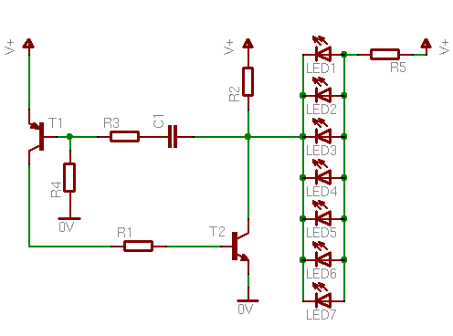
8 components! The complete circuit is made of 2 transistors, 5 resistors and one capacitor. It can be made extremely portable. The batteries will be significantly larger than the PCB itself. For more portability, coin-type batteries can be used instead. The power that this circuit needs is extremely low, and even very small batteries can have quite a long life.
On the 11th of January 2010, i turned on this circuit with a pair of rechargeable batteries, 2500 mA fully charged. I run this circuit day and night to see how long the batteries would last. The circuit kept running until the 23rd of March! That is 71 days of continuous operation, more than 1700 hours! Of course the LEDs were very dim the last weeks and could not be sued for security light, but it still flashed.
To make this application legal for on-road use, i had to check the Vienna Convention on Road Traffic. For the rear signaling light it says:
A light without a steady mode is considered approved only if it flashes at a constant rate of between 60 to 240 flashes per minute and has a luminous intensity of at least 4 candela.
The second pard is covered by far, as each LED is ultra bright with luminosity 11000 mcd. As for the first part, it describes the pulsing frequency. It must be between 1 to 4 Hz. My first design was around 1.2 Hz pulsing frequency. I chose such a low frequency, because i wanted to extend the battery life as much as possible. The result was rather... boring... The LEDs were flashing once per second. And believe me, it really does not sound as slow as it is. So, i decided to increase the pulsing rate up to 2.6 Hz, a little bit faster than the car's flashing direction lights.
Another circuit parameter that i experimented was the pulse positive period. This is the time that the LEDs will remain ON. This was rather difficult to choose. I had to find a setting that would keep the LEDs ON long enough to be seen, but not too long because they would drain the batteries faster. I ran some experiments in a dark road about 100 meters long. After many tries, i decided to keep the positive period between 10 to 14 mSec.
Bill Of Materials
Resistors
R1
Resistor 220 Ohm 1/4 Watt 5% Carbon Film
R2
Resistor 220 Ohm 1/4 Watt 5% Carbon Film
R3
Resistor 2.2 KOhm 1/4 Watt 5% Carbon Film
R4
Resistor 4 MOhm 1/4 Watt 5% Carbon Film
R5
Resistor 1 Ohm 1/4 Watt 5% Carbon Film
Capacitors
C1
47 nF Ceramic Capacitor
Transistors
T1
BC327 Switching and Amplifier Applications PNP Epitaxial Silicon Transistor
T2
BC547 Switching and Applications NPN Epitaxial Transistor
hi !
i have made a flashing circuit ,but based on 555 ic . when i add more then two smd led the light gets very dim. any idea if i can add 16 or seventeen smd led on this circuit , i run it on 12 volt. lipo.
appreciate to reply
@Newbie here C547 is ok, do id the 5M resistor. The 47 aec is something i do not know. A "47" or "470" by itself means 47pF. For 47nF the capacitor should be marked "473"
@Colin I really want the 2.4v.Is it okay that the store gave me a C547B transistor instead of BC547 and a 5 Mohm resistor instead of 4Mohm resistor,they told me its the same?I also want to know if 47/aec ceramic capacitor is same with 47nf?? Im really dont have a knowledge about electronics,but im interested doing this project..
At 16 December 2014, 13:24:28 user Colin wrote: [reply @ Colin]
"mine only stays on,doesn't blink.I dont know whats wrong.any tips"
The first tng to do is increase the voltage to 4v5.
I was wondering whether you have found the formula to change the frequency and duty cycle of the oscillator by altering the C and R values. It would be of great help. Thanks.
I was considering building this great circuit, but before I buy it I have a question: which resistors do I have to exchange to increase the frequency of the blinking? I was thinking about something like 30-50Hz. Or is there a formula to calculate the resistance needed?
Just Ask Yourself "Why Is It Have To Be between 1 Hz and 4Hz ?" Who Gives Them the right to make it law? Why must have more power than another? the same thing goes with drugs like "weed" any one who has smoked it has never killed any one yet but its illegal, but u can go buy penicillin (its in banana's... its stops the heart in high dosages if in blood stream or in stomach) yet you can go buy it at a pharmacy for cheap and a lot of it too
@Jess no you cannot use this circuit. You need either a boost power supply with constan current output,(i dont have something to show you though) or a simple constant current like these:
At 27 September 2012, 5:41:43 user Jess wrote: [reply @ Jess]
Hi Giorgos,
I wan't to create a steady LED Lights using 2-pcs. AAA batteries. Can I use the circuit "Miniature 2.4 Volts LED Flasher" by removing the transistors?
Or do have other simple circuit that uses 2-AAA batteries for a 7-LED steady light source.
@DanD i do not have such a circuit ready, and i would reccomend making it with a low voltage microcontroller instead.
As for the alkaline rechargeable, frankly speaking this is the first time that i hear. i will check them out though for i hate this 1.2V
At 25 January 2012, 17:15:14 user DanD wrote: [reply @ DanD]
@Kammenos @Kammenos
I will design it using 4 "aaa" batteries as a power source. Is there a circuit already designed to to the chase or sequencer where one lights up, stays lit then the next one etc. until all are lit?
Are you familiar at all with the rechargeable alkaline batteries? ( PureEnergy in Canada makes them and they are supposed to output 1.5v)
@DanD @DanD No this is not possible with this circuit. This is only a low power LED flasher.
At 25 January 2012, 1:07:08 user DanD wrote: [reply @ DanD]
Just what I'm looking for, however I would like it to do two things - chase or sequence the led's so they light up one at a time (rapidly) and when all are lit go dark and start the sequence again and again for about 100 seconds then shut off, and the start cycle is activated by a key-chain remote controller. Is this possible?
@Phillip M. Feldman The circuit runs at 3V, and each LED draws about 15mA (if i remember well). 7 LEDs means 105mA, which eventually means about 100mV voltage drop on the resistor. The resistor was used to further decrease the power used by the circuit. It was an experimental model.
@Fung two LEDs in series would require double the voltage to light, so the would not light at all.
At 5 June 2011, 11:28:58 user Fung wrote: [reply @ Fung]
Would the power delivered to the LEDs be not enough if connected in two by two (ie 2 LEDs in series, then connect them in parallel with other pairs)?
Also, after viewing the image concerning R4, the actual value of that resistor is 4.7Mohm, not 4Mohm. I found that the 2nd band is violet but not black.
This is one part of the case. there is something else. LEDs have a huge voltage drop compared to the power supply (2.4). Actually, most of the voltage through R5 drops across the LEDs. Without R2, the capacitor would never exceed the remaining voltages.
At 4 January 2011, 20:26:48 user Steve wrote: [reply @ Steve]
Thanks for the quick response but I am still confused. I understand the circuit to work like this: Power is applied, T1 and T2 are open, C1 begins to charge through R2 and R5(plus LEDs). While C1 is charging the LEDs are on since most of the current to charge C1 comes through that path since R2 is much higher resistance. Once C1 is adequately charged T1 closes and therefore T2 closes which discharges C1 through T2. When C1 is adequately discharged T1 opens therefore opening T2 and the cycle starts again. With that as my understanding I think C1 mostly charges through R5 and that makes R2 irrelevant. Now as I\'m writing this I may have answered my own question. As C1 nears fully charged it draws less current. Perhaps when the potential across the LEDs is not enough to light them up they act as open circuits. This would mean that R2 is needed simply to top off C1 after the potential across the LEDs becomes too low. Is this the case?
R2 is used to charge the capacitor C1, when T2 is in cut-off
At 4 January 2011, 19:43:44 user Steve wrote: [reply @ Steve]
Can you please explain why the R2 to V+ connection exists in this circuit? I am new to electronics and I can\'t figure out what purpose R2 to V+ serves. The best I can come up with is that it reduces the current through the LEDs, however, R2 is so high in comparison to R5 that the decrease in current seems irrelevant.
The LEDs have probably 3 volts (or higher) forward voltage. They will not be full bright with no way. First of all, the 10 ohms resistor is too big. You need to have 1 ohm. To have full brightness, you can either increase the supply or use LEDs with less forward voltage.
At 2 January 2011, 16:40:24 user Fung wrote: [reply @ Fung]
I use 2.6V to power the circuit (2xAA, but only 1.3V each), 10R for R5, and 4 white LEDs are used. But the LEDs are not bright enough, if R5 unchanges, should I increase the supply voltage?
At 11 November 2010, 10:31:07 user RICK wrote: [reply @ RICK]
WHAT A INCREDIBLE CIRCUIT!! LOW PARTS COUNT,EASY TO BUILD AND & 7 LED'S!! A WINNING COMBINATION!!!
Well, yesterday (March 23) the batteries died. The circuit ran continuously for 71 days, more than 1700 hours! The last weeks the LEDs were too dim for the circuit to be useful though, but it still was flashing.

 Home
Home
 Projects
 Experiments
 Circuits
 Theory
 BLOG
BLOG
 PIC Tutorials
 Time for Science

 Contact
 Forum
Forum
 RSS
RSS


 Reddit this

