This is the first capacitance touch sensor that i present, in continue to the Resistance touch sensor and the AC Hum touch sensor.. I had to decide if i would start with a PIC-based or with an analog circuit. I decided to start with a PIC-based touch button for two reasons: First, i thought that a simpler and compact touch circuit is more practical, even if basic knowledge of PIC programming is needed. The second reason is that i had the proper PIC in stock, but i was still waiting for some parts that i purchased a few days ago, for making an analog touch button...
If you want to get some theoretical knowledge about touch sensors in general, i suggest you read the theory of touch sensors that i have.
The circuit
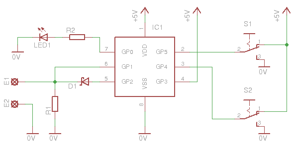
A microcontroller always makes things simpler. Look at the following schematic:
The operation is as follows. I use the internal comparator of the pic connected as a relaxation oscillator. The frequency is determined by the resistor R1, and the capacitance of the touch sensor. The following picture is a screenshot of the oscilloscope screen, with the probe connected at pin 6 (GP1): (click to zoom in)
I use a double sided board for electrode
The touch electrode is connected to pads E1-E2. The electrode must be designed in a way that it performs a capacitor with the ground. Either use a 2-sided PCB (as i do), with one side connected to the E1 electrode and the other to ground (E2), or use a single sided with 2 regions, the electrode and the grounding layer. I really encourage you to read the theory of touch sensors to learn more. The frequency that my setup runs at is about 94.5 KHz. You can change the frequency by changing the value of R1. The greater the value, the less the frequency. This frequency is then driven to the the Timer0 module of the PIC through the prescaller. From that point, the software takes control of the operation.
The Software
Testing the software. The oscilloscope really helps! Sometimes i wonder myself, why hadn't i got this years before... I use two digital outputs of the PIC to transmit (temporarily) the frequency count, so i know what i deal with and i can select a resistor easily.
To measure the frequency, first i reset the timer0 module, which also resets the prescaller counter. Then, i run a fixed delay, in my case this is 60mSec. When this delay is finished, i acquire the tmr0 and the prescaller value, to make a 16-bit (sort of) value, the TMR0:Prescaller. Actually, this is not 16 bits. The problem is with the prescaller. There is no immediate way to read the prescaller. To get its value, i increase the prescaller with the PIC's internal oscillator (Fosc/4), and i measure how many loops are required to increase the tmr0 value.
Let's see an example. Suppose that the delay finished when the prescaller was at count 64. I cannot read the 64, instead i can keep on increasing it until i notice an increment on tmr0, which means that the prescaller has overflow (from 255 to 0). This will happen in 192 pulses (256-64). But here comes the real problem. The routine that i use to measure the pulses and check tmr0 for overflow, is 6 instructions long, which means that i can only count once every 6 increments. Suppose now that the prescaller has stopped at 0x00. It will take 256 (255+1) instructions to overflow, but i will only be able to measure 256/6 = 42.6 (ceiling=43). So, the 16-bit pair is not exactly 16 bits. The 8 bits of the HIGH byte comes from the tmr0 which are indeed 8-bits, but the 8 bit for the LOW byte comes from the prescaller, and they can only climb up to 43. This is not a real problem if we do know this detail.
Now i have to determine if the touch-pad is touched or not. To do so, i need to check if the frequency is changed. But how do i know what the frequency was originally? Well, i do a trick for this. First, i added a pair of constants, which i named GLPressHysteresis_H and GLPressHysteresis_L. During start-up, the PIC measures the frequency of the relaxation oscillator, and from this it subtracts the 16-bit number GLPressHysteresis_H:GLPressHysteresis_L. The result is the press threshold value. When this step is completed (during start-up), then it continuously runs a loop during which it measures the frequency and compares it to the press threshold value calculated before. If the frequency is lower than this threshold value, then the PIC considers this as a key-press.
With this trick, i save a lot of testing and setup time of the electrode. That is because, even a small small change of the position or the cover or the distance of the electrode, results in different oscillating frequency. The PIC automatically detects the quiescence frequency during every start-up. But this has one drawback. If the sensor is touched during start-up, then the frequency that will be calculated will be wrong. You can change this easily in my code, by simply replacing the calculations with a fixed value, but i do not encourage you to do so, unless you know what you are doing and you are familiar with assembly sheets.
Regarding the key-release, i could have used the same set of threshold values, but that would cause a malfunction, because there are times that the electrode is barely touched, yet it is still acknowledged as a touch. Whenever this happens, the output is not stable. It turns on and off randomly. So i added another set of threshold constants, which i named GLReleaseHysteresis_H and GLReleaseHysteresis_L. They also perform a 16-bit long number, which is slightly lower than the press threshold. The difference between these two thresholds is the hysteresis. This hysteresis really saves the day regarding the touch-release recognition, and really works with no problem.
Here are the files with the firmware. First, the full assembly listing sheet to compile and upload:
Actually, these are no switches. These are setup-pins which determines some parameters of the touch sensor. First of all, S2 which is connected to GP4. This controls the sensitivity of the sensor. If you look at the code, you will notice that i have two pairs of press and release threshold values. The first pair is for low sensitivity and the second for high sensitivity. If GP4 is connected to LOW, then the sensor will have low sensitivity. If it is connected to HIGH, i will have higher sensitivity. This is an easy setup for those who want just to upload the hex on a PIC and make a switch. Keep in mind that this change needs a reboot to become active, just as happens in every big (or small) change on windows...
The switch S1 changes the touch sensor operation between a temporary make button (touch button) and a toggle switch. If GP5 is driven LOW, then the PIC operates as a pushbutton. The output is active only as long as the electrode is touched. If it is driven HIGH, then the output toggles between ON and OFF each time that the electrode is touched (and then released of course). This is again for those who have no idea of PIC programming but still are able to upload a hex file on a PIC. Unlike the previous switch (S2), this one can be changed during run-time. No reboot is needed, just as happens in most small (or big) changes on Linux...
Operating as pushbutton: When the electrode is released, the output is deactivated
Operating as pushbutton: When the electrode is touched, the output is activated
Operating as toggle switch: The output is toggled ON and OFF on each touch
Operating as toggle switch: Now the output is ON
Will this work no matter what?
No, it will not. There are some things that may go wrong. The most simple issue that i can think of, is the frequency of the relaxation oscillator. My setup oscillates at around 95 KHz. But this is almost impossible for you to achieve with the first test, because this has to do with the touch pad itself. Different touch-pads will result in different oscillation frequencies. If your frequency is close to mine, then it will operate normally. But if there is a large difference, two things may happen: If your frequency is way too high, then the TMR0 will overflow. If this happens, then the results will not be as expected. It may sense a touch, or maybe not. The point is that it will not operate correct. If your frequency is too low, then the touch will not be able to reduce the (already low) count enough, and the PIC will never be able to sense it.
If you notice a strange behavior after powering up the circuit, then it is time to turn on your oscilloscope. Measure the frequency at PIN #6 (GP1). It should be around 95 KHz. If lower, reduce the value of resistor R1. If higher, increase it. Keep also in mind, that if the electrode introduces a very large capacitance to the circuit, the the body capacitance will not be able to change the overall capacitance of the circuit in a noticeable way, and so the switch will not operate.
Capacitance sensors have many tricks hidden when designing the touch pad, and for this, some people call the designing "an art". I don't see any art whatsoever. I only see different geometrical characteristics that needs to be taken into account, and lot of experience that the designer must gain through trial and error. Simple small rectangular 10x10mm or 20x20mm, or even circular touch pads are guarantee to work. Good luck.
I want larger touch pad, and i mean LARGER. Can i?
A 10pF works fine for me
Sure you can. But this requires a slight modification. Instead of a 2-regions touch pad, you will use only one region touch pad. You do not need to have a grounding layer. That is because, if the grounding layer is big like the touch pad, then the capacitance that will be created will be very big, and the body capacitance will not have any great influence. Therefore, a small 10pF capacitor must be added. The capacitor is connected at the electrode pins E1 and E2. The smaller the capacitor, the higher the sensitivity of the circuit. But smaller capacitor also means higher frequency of the relaxation oscillator. So you need to choose a capacitor that will not break the rules discussed before. A 10pf works fine for me. It should fit for you as well.
Then you connect your large touch-pad to E1. Look an example:
This piece of aluminum foil is now the touch pad. As a matter of fact, this is no longer a touch-sensor, but a proximity sensor. The surface of the pad is so large and the circuit sensitivity so high, that it can sense my hand from 10cm away:
Dear Sir,
Many thanks for this interesting project and nicely explained.
Before going to hardware experiments I was trying in Proteus Simulator loading your Hex file. A Touch pad is available there. But I am not getting the Schoktty Diode BAT 85. I have tried with other Schoktty Diode(PMEG3010EH) available in Proteus Library, but overall it is not working.
I am also not getting any output/Frequency at GP1.
Kindly explain in short the Schoktty Diode working here.
My other questions are :
Number of similar diode that will work.
Will it work in Proteus Simulator?
Thanking again,
Regards,
Debabrata
i`m so glad have found your page. i will try to make this project. its very awesome if i can apply this circuit to my some touch button project. one question, what is the function of the D1 ?, can i replace it with other part number ?
@adel got though the theory http://pcbheaven.com/wikipages/How_a_Touch_Button_works/
At 6 February 2014, 14:58:08 user adel wrote: [reply @ adel]
hy, I need to do the same code but in c code with a aduc842,
I would like to know how to measure frequency?
it is the frequency that will change depending on the capacity
@Rex T Not really possible with one sensor. You have to design a matrix of sensors, more than one.
At 7 December 2013, 17:42:21 user Rex T wrote: [reply @ Rex T]
Suppose i want to make a big sensor and i want to count the number of hands kept on the pad.If two hands are kept one by one,the counter should be incremented accordingly.If any hand is removed it should decrement.And this counted value should be compared with a threshold,for example:2 hands..How do i go about this.And thanks for the information.
At 4 November 2013, 12:26:18 user alex wrote: [reply @ alex]
hi
iwas wondering how posible it is to make a sensor which translates body movement-dancing- into sound waves...could be best solution a circuit similar to your touch sensor?...any ideas or advice plz?
Hi Giorgos.
I'm impressed by your touch switch.
I'm just working with PIC but i don't know the assemler code.
Do you think it is possible write the code in C?
Hello Giorgos
First thanks for your fast response
I am confused
If I will put yours hex file in to 675 or 629 will work?
Yes or no. Sorry I am not in this field. I want to checked if can be integrated in one of my simple project
@echogate During your experiments you will notice that even moving the same electrode can change the frequency a lot! Capacitance sensors are extremely sensitive. When you fix it and put it in the housing that you plan, it must not move otherwise it will change state
Thanks for your helpful suggestion!! Adding on the 1pF most definitely stabilizes the circuit a great deal, but in order to duplicate the above video presentation, my frequency needs to be set to 156kHz with the R1 at75k%u2026why is there so much of a difference in my experiment comparing to yours? I%u2019ve made about 10 different electrodes ranging from 4-12pF (connected to a small wire) just to see if I can bring the frequency range down, but no dice so far. Next, when I get the time, I%u2019m going to hardwire the circuit to see if I can bring the frequency close to yours of 95kHz. Thank you!!
@echogate Welcome! First do the trick of the stable capacitance - add a small capacitor across the electrode pads, as small as 1pF. Use very small wires for the electrode. Once you give power, do NOT move the electrode! Better use duct tape to fix it somewhere and then give power. This is very important.
Hello to all posters on this great forum!
This is incredibly fascinating project, but unfortunately I am having a problem of duplicating it as shown in the video for many reasons as correctly stated by the creator of this project. I%u2019ve been electronic hobbyist ever since I can remember, but had to give it up while back because of my occupational time restrains. Now I am back after many years hoping to encourage my teenage son in electronics and this is a perfect project for it.
Can any one of you good people here that were able to duplicate the working order of this project (as shown on video) measure up your total touchpad capacitance value, so I can reproduce it ? That would really help me a great deal.
I%u2019ve made up a number of touchpad electrodes in various sizes out of old 2-sided PCB ranging from 8pF to 27pF which also required me to double up the value of the R1(47K) to maintain the 95kHz range, but the circuit is still unresponsive, unless I physically touch one of the electrode conductors. I believe my problem is caused by the touchpad electrode.
Thank you in advance!
@Carlos Aguero It should work with batteries as well. Other people have done this:
http://pcbheaven.com/opendir/index.php?show=59597079mo59598165bt545cfce2
It works great!! good project... but if I use it with a DC supply(ungrounded) like a battery, it does not detect the frecuency change... it has to be a DC supply with ground connected to 0Vdc.
I want to install a touch switch in my car to lock/unlock my doors, is there a way or a trick to make it work with a battery?..
Greetings I congratulate you on your project, compile the program in MPLAB and I get many errors you know what, I would like to implement it with 12f508, Thanks
@ADITYA Start from here:
http://www.pcbheaven.com/picpages/
At 21 November 2012, 11:10:08 user ADITYA wrote: [reply @ ADITYA]
Hi
Friends i have no idea about programming but i want to workout this project . so i need help regarding the programming language n program . Can i get some help please.
%u0131 registered form
but I could not find where the error file will install the
open and there I installed a new topic
I'd appreciate if you help
Why is the error? Giorgos Lazaridis
the code gives an error, I derleyebilirim how to do it?
or re-write ccs c?
At 4 September 2012, 11:27:59 user DoDo wrote: [reply @ DoDo]
...
subwf passarg1,w ; R= TMR0 - HIGH threshold
btfsc carry ; skip if carry=0 ~ R<0
goto IsNotPressed ;If R < 0, Button is Pressed
;Else is NOT pressed
...
to avoid misunderstanding
At 29 August 2012, 8:38:24 user DoDo wrote: [reply @ DoDo]
Can you write code to do this things: like toggle but not change the LED state when hold or release.
@chris is it? oh! i thought it was 5V PIC... so you can run it at 3V. Use smaller diode for R2 of course... and maybe R1.
At 24 August 2012, 17:55:30 user chris wrote: [reply @ chris]
Thanks for your answer. But if the problem is with the pic then I dont understand coz in the attached pdf for the PIC12F615 it says operating voltage 2 - 5.5 volts. Am I missing something?
@GEGE I'm sorry but i cannot answer that for sure. It is certain that you will need to make changes to the code no matter what. But this i cannot do it.
At 19 June 2012, 3:14:32 user GEGE wrote: [reply @ GEGE]
Dear Giorgos,
I had search locally, couldn't find 12F615 but I 12F675 SMD is available.
can we use this uC? can you send the HEX for the PIC12F675 for this project?
Thanks Bro,
GEGE
@Sashika as i explain, the problem with the 555 circuit that i posted is not very reliable. maybe i will think of another linear circuit or i will use some sort of frequency to voltage chip, which will increase the overall price.
By the way do u have any idea abou how to use NE555 as capacitance sensitive touch switch? If you can please post a circuit diagram here.. :)
However i found this circuit.. Bt some details are missing.. Vcc , Q1 and Q2... If anyone can please help me to find those missing details becouse im a beginer.. Thank you.. www.siliconfarmers.com/post/2011/02/27/555-contest-entry%u2013touch-sensor.aspx
At 23 April 2012, 17:19:14 user GEGE wrote: [reply @ GEGE]
Thanks Giorgios.
I have no experience with PIC. about 20 year ago I had play with 8051, but now is gone from my memory.
I will start to look at your PIC tutorial. Just wondering would find a ISP downloader using USB port. My notebook has no more RS232 port.
may be a little direction of making simple ISP downloader or surfing the PIC tutorial easier or this very old man are most appreciated.
again thanks giorgios.
At 18 March 2012, 19:25:14 user Ion wrote: [reply @ Ion]
@Giorgos Lazaridis
Thank you for update
If you would like to play with 18f , even for mtouch i can FedEx you a module to play
I mean, for my experiments i designed and made a dip adapter from 80 TQFP to DIP 40
I can send you one with the chip on it
It is not for CVD but just for you to use it when ever want to play in a project, because it is portable for any breadboard
Send me a PM with an address and you will get it
@Ion i don't have currently a 18 other than some qfns for USB projects that i prepare to make (hopefully within this decade). I will make it with my favorite 16f1937 (or 1939 maybe), but the procedure will be the same for all pics with a/d. When i go with 18f i will start with this mtouch...
At 18 March 2012, 18:34:24 user Ion wrote: [reply @ Ion]
@Giorgos Lazaridis
Thank you Giorgios.
If you can this time make it for a pic18f you will make lots of peoples happy
The 16f users can enjoy the benefits of your previous projects with cap sense, but us the unlucky users of p18, stuck with a dirty mtouch which never works, we are waiting for help to come and bring peace to our soul :)
Personally i am close to get insane because of that. I am stuck with a done project just for this. Of course i can use two CPU and finish it, but for me will look ugly and i do not want to do it as long as i believe it must be a proper way to do it (aka i believe in you)
@Ion For a reason i cannot explain, i haven't upload the example (??????) and i cannot find the code in my PC. Some months ago the hdd crashed and i lost lots of data, but that does not explain why i did not upload the CVD example... Strange. But when i return from a business trip that i am, i will make it again. I wonder what i've done the original circuits and why (oh why) i forgot to upload it...
At 18 March 2012, 7:13:31 user Ion wrote: [reply @ Ion]
@Giorgos Lazaridis ,
Giorgios, I think i will become insane soon
I tested over 25 examples from the web using capacitive voltage divider, all work, but i MUST touch the button
On your video, you had a heavy piece of plastic and did works.
Please be so kind and post the code on that video.
If you really want to help me, will you be so kind and adapt it for a pic18f series ? ...18f87j90 ?
If not, i will try to do it by myself which will be a great challenge as i do not know assembler
Thank you
Ion
At 18 March 2012, 1:45:28 user Ion wrote: [reply @ Ion]
@Giorgos Lazaridis
Hello Giorgios,
This is the link of video where you explain how the capacitor sensors works
http://www.youtube.com/watch?v=0GmIkyEzHnk&list=UUNH0a2xuMMZec8ok61GzVeA&index=30&feature=plcp
As my pic does not have cap sense, and my knowledge on microcontroler are limited, as was curious to test this method - CVD .
I did build your examples for cap sense in pic16, works like a charm , so i have a strong confidence on your coding methods.
For this i am looking for that piece of code , explained in the video, to adapt it at my pic18.
Thank you
@Ion for some reason i remember that i have studied this method, but i cannot recall this video nor any example that i made... strange. in which video i tell this???
At 17 March 2012, 18:38:55 user Ion wrote: [reply @ Ion]
@Giorgos Lazaridis
Hello Giorgios,
On your you tube video about capacitor voltage divider you said that i can see the code on your web site, but unfortunately i do not see it.
Will you be so kind and post the link of the code for CVD
Thank you
Ion
Thanks for all the help guys, it was a cheap plug-top PSU,tried the Caps first which slightly lowered the effect then swapped to a Desktop Switch-mode PSU and it works well and free of any "hum".
At 9 March 2012, 14:25:44 user Ion wrote: [reply @ Ion]
@Rakavich i believe the power supply pack it is not properly grounded.
Can you scope it and post the pictures of the output after 7805 ?
Firstly Wonderful Website so much useful info,
I built your circuit which worked great when powered by a bench power supply, I have the output powering a Relay to power an LED strip (9V), and the touch electrode is a length of anodised aluminium.
The only problem I have is I am now using a 9V Regulated plugtop supply using a 7805 to supply the circuit, it works fine but if you gently touch the sensor or gently rub your finger over the Electrode you feel "vibrations" is there anyway to remove or lessen these?
@Ion check out this one:
http://www.pcbheaven.com/circuitpages/10_buttons_touch_pad_bcd_output
At 25 February 2012, 22:37:28 user Ion wrote: [reply @ Ion]
Do you have a circuit cu one micro si 4 or 5 touch switches ?
can you post please the code and schematic?
Also i am interested to know if i use one micro si press touch 2 sensors in the same time, will be sense one or two ?
At 16 January 2012, 0:38:55 user deaf wrote: [reply @ deaf]
Hi Dear
I'm deaf. It felt like coming from that. Please send me picbasic pro...
Thank you very much
@kerok no, not directly, it must operate at 5v. You can add a 7805 to get 5v out of 24 v, and then add a relay to the output to control any load you want.
At 31 October 2011, 17:57:02 user kerok wrote: [reply @ kerok]
Hello,I have question for you. Is it possible to make the same button, but on 24v?
I need to connect it with plc drive.
@Qla i saw your video and it looks like that you made a very nice touch button. You will find yourself that if the touch button is correctly installed (firm and stable hardware), it will be a very reliable switch. My touchbuttons work extremely well! Better than i thought they would. Microchip has done a very good job with this module.
At 9 October 2011, 22:37:57 user Qla wrote: [reply @ Qla]
Hi again
I don't have much time for fun so SMD version will have to wait a while..
But in I have done 5 switches circuit (4 toggle and 1 temporary make button with 3sec off delay) and put it in my car:
http://www.youtube.com/watch?v=ByWTRBv5cAw
the small version of touch button was small enough to put it behind "blind" buttons so have no need to make smaller SMD version for now.
I have deleted high sensitivity mode from program, slightly changed values of press/release constants and increase start delay from 1 to 2 sec (this last change is not necessarily I think, but did it anyway)
After 5 days of tests in my car I can tel it works very good (in my town more often I stand in traffic than ride so have a lot time for tests :) ).
Relay for each "button" is 1,5A what is more tan enough for me.
For now I use 3 of 5 buttons switching on inside LED lights and now integrated with car remote for the gate (under temporary make button)
At 28 September 2011, 14:00:29 user Qla wrote: [reply @ Qla]
You will have to wait the while for it ;)
Now I'm experiment with code:
-slightly changed values of press/release constants
-since touch-pad size will be fixed and integrated with circuit I have removed HIGH sensitivity option from code - one track on PCB less :)(well - I think I've done that - not tested that code change yet)
I'm just learning assembler by myself from on-line tutorials so it takes me some time to understand the code.
Project PCB to be so small and have S1 option is hard task, but I think I almost have it.
@Qla i look forward to see the result tiny SMD PCB and a video, to feature it in my site. It makes me very happy to see people getting ideas from my site to build their own circuits and PCBs and have fun ;)
At 24 September 2011, 19:34:23 user Qla wrote: [reply @ Qla]
Tests - supplemental:
Have tested other 3 of my sensors and appears that one works fine with 2pF capacitor; other one with 1pF and last one works best with no capacitor added (even with 1pF sensitivity was to low)
So it strongly depends on exact value of 47kOhm resistor and touch pad size and need to be tested with value of eventual capacitor.
After all I think changing value in assembler, recompile and reprogram PIC will be the best option.
Earlier I had problem with compilation under MPLAB so have programed PIC with hex file only.
Now when I know that MPLAB shows hundreds of errors during compilation because it see the difference between BIG and small letters in assembler code, and switching on the option to ignore that fixes the problem - now I can have fun with asm code :)
Thanks for the tip Kammenos
I want to make this all on SMD modules and designed PCB to make all thing really small (1x1x0,5cm I hope) - will put here pcb and changed program if this succeed :)
@Qla thanks for sharing your results with us! One question: how do you program the PIC? I mean, you use the assembly listing and recompile, or you upload the hex file? If you can change the assembly listing, you can control the sensitivity of the circuit with great accuracy according your application. There are 2 sets of parameters. Set 1:
GLPressHysteresis_H, GLPressHysteresis_L, GLReleaseHysteresis_H, GLReleaseHysteresis_L
and Set 2:
GLPressHysteresis_H_2,GLPressHysteresis_L_2, GLReleaseHysteresis_H_2, GLReleaseHysteresis_L_2
These are 16-bit numbers (H and L at the end of each parameter indicates the HIGH 8-bits and LOW 8-bits). By increasing the values, you decrease the sensitivity and vice versa. You only need to change the values of on set (for example the set with the _2 at the end) and select it according to the hardware button that i have ad which selects sensitivity.
At 23 September 2011, 17:48:44 user Qla wrote: [reply @ Qla]
Ok
Have done some tests with 1; 1,5; 2,2; 3 pF capacitors put between sensor line and GND.
Seems that 1 and 1,5 pF capacitors didn't help to much.
I have tested 5 models of sensor (witch are almost the same but have slight differences in touch-pad size and 47kOhm resistors - they may have +/-5% error by the fabric but I have select that witch have less than +/-0,2 kOhm from 47 value)
Depends on model there was 2,2 or 3 pF best choose to add (more could cause big sense range decrease)
Adding 2,2 or 3 pF I almost eliminated very high sensitivity cases (less than 1 in 50 power ON I think) and still have good sensitivity i normal run.
Also it is worth to say that if You use single button and don't have metal parts or other buttons in 2cm range than You don't need any capacitor (just sometimes it will be more sensitive), but in case you have less than 1,5cm free space between sensors than from time to tine You will turn on 2 at once when touching only one of them..
At 22 September 2011, 21:56:48 user Qla wrote: [reply @ Qla]
Hi again.
My reset button is very simple - it is the temporary push button that switch off +5V when You push it and it is ON when You don't touch it.
I have done some experiments with capacitor between sensor line and GND.
2pF works just fine for me - have done over 50 torn off and on power cycles checking sensitivity - not even once touch button was over sensitive.
It was always turn on diode when my finger was 4-6mm from touch-pad and turn off when finger was 2-3mm from it (air separated).
Before adding capacitor 1 or 2 times on 10 it was turning ON when finger was 1,5-2cm from touch pad and other times it was working OK (about 5mm from touch-pad).
So I can suggest that adding 2pF capacitor (or less - i will do more tests tomorrow when I will buy some capacitors with less capacity) between sensor line and GND makes the circuit more stable.
Regarding the keycode-lock - yes I have seen it (and read it very careful - very good job by the way) but since I need 1 to 4 buttons in one place and would have ti make toggle switch circuit to each line than I want to make simpler circuit works better, and I think that I did it by adding that capacitor to the circuit.
@Qla hav you seen my keycode-lock?
http://pcbheaven.com/projectpages/Servo_Actuated_Door_Keylock_Hack
The touch pad works so good, that i hardly believe it. I got a headache and made 3 (or 4 i am not sure) different PCBs with different touch layouts. It was very difficult to find the right size of the pad, and the right distance of the grounding layer. You may want to see the PCB design that works extremely well and reliable for me:
You may want to experiment some more with the capacitance sensors. Microchip states that designing the touch pad is a difficult job that requires experience. And they are right. I have not test the circuit that you are building now in a long period, but it worked fine for me when i built it. I hope that the mistake is not from my side.
Regarding the reset, there is a 1 second delay from the time that you power on the device and the time that the routine starts, to avoid powering problems. GP3 is the reset pin. You can unhook it from the +5, and then connect it again to the 5v through a 22k resistor. Then connect a 22uF capacitor from the same pin (GP3) to the ground. This will make a lousy reset on power-on circuit. You may also want to google for a PIC power-on reset circuit with a transistor.
At 22 September 2011, 14:29:32 user Qla wrote: [reply @ Qla]
Today I will test the circuit with 2-5pF capacitor between sensor line and GND - may be this will help..
When I was testing 4-buttons multi-touch circuit and put 10pF capacitor instead of 1 touch-pad - the other 3 seems to work much better - may be coincidence - I didn't test it for long..
At 22 September 2011, 14:09:25 user Qla wrote: [reply @ Qla]
I use it in couple places - in my PC (plastic front) with transistor to light up my keyboard:
http://www.youtube.com/watch?v=cO-Dma7EwJs
Most times it is OK but sometimes it is more sensitive and metal parts (more than 1 cm from it) disturb its work (i solved it by adding "reset button" that I don't have to turn off and on PC or take off front panel,
also I have 3 of them in my car (turn on and off inside lights) than sometimes also they are more sensitive and turn on when I touch other sensor (at least 1,5cm free space between sensors),
when I make test witch sensors stick to some plastic sheet with at least 1cm free space between them - form time to time one of them is more sensitive and turns on when I touch other one.
I don't touch them and remove all metal things from nearby when turn power on, and I don't move it during the test.
I can live with that, but it is necessary to have reset button hied somewhere so I was wondering if You have similar problems with your sensors and may be solved it :)
I wonder how LIVOLO solved that with their house light switches - also capacitive and based on PIC16F690 but i suppose they will not give the program code and also put Code Protect on their devices :)
@Qla If the circuit works fine 9/10 times, then i can safely suppose that the circuit and code is ok, as well as the implementation you've done.
During start up, the PIC runs an initialization routine and sets the "quiescence" frequency (when he touch pad is not pressed). If after startup the touchpade changes position or is moved for any reason, then this frequency changes dramatically. Could this be the case? Here is a test: Put the circuit somewhere stable, so that it cannot be moved. Then make test-runs to see if the problem occurs again.
Regarding the capacitor, the more the better. You should have at least one 1uF capacitor even if you use a battery. In my projects, i usually have 1uF and 0.1uF for low and high frequency filtering and decoupling.
At 22 September 2011, 12:46:25 user Qla wrote: [reply @ Qla]
When it is power on from LM7805 there is 100nF capacitor on +5 line and also made tests with additional 1uF capacitor - no difference. When power is from battery cartridge there is no capacitor.
You say there should be or shouldn't be capacitor to make it work fine every time?
May be additional capacitor on power line near pic? What value?
@Qla have you put any decoupling capacitors across your power supply?
At 22 September 2011, 12:09:26 user Qla wrote: [reply @ Qla]
Yes touch pad is made from 2 side PCB and layer near the pic is ground (connected to 0)
At 22 September 2011, 12:06:17 user Qla wrote: [reply @ Qla]
And as I describe before most time it works just fine, but from time to time (1 on 10 power On pic) it is very sensitive and after reset (power off and on) it is back to normal.
Than always have different sensitivity when it is OFF and you turning it ON (more sensitive) and when it is ON and you turning it OFF.
I have made couple of them and all works in that way.
Touch pad has about 1,5 x 1,5 cm surface - I can easy decrease it using grinder but since touch-pad is stick to the PIC it is irreversible process.
Than because of most time it works fine, than I figured out that 10% of wrong working is just adjustment process breakdown.
Thanks for interesting and response Kammenos
At 22 September 2011, 12:05:22 user Qla wrote: [reply @ Qla]
And as I describe before most time it works just fine, but from time to time (1 on 10 power On pic) it is very sensitive and after reset (power off and on) it is back to normal.
Than always have different sensitivity when it is OFF and you turning it ON (more sensitive) and when it is ON and you turning it OFF.
I have made couple of them and all works in that way.
Touch pad has about 1,5 x 1,5 cm surface - I can easy decrease it using grinder but since touch-pad is stick to the PIC it is irreversible process.
Than because of most time it works fine, than I figured out that 10% of wrong working is just adjustment process breakdown.
@Qla is there a grounding layer underneath the touchpad? The touchpad must have a grounding layer. For example, you can make a touchpad with 2-sided PCB, top layer is the capacitive sensor ad bottom is grounded to GND. This makes the circuit more stable
At 22 September 2011, 11:45:16 user Qla wrote: [reply @ Qla]
In my old version I had about 10cm wire and You have right it was unstable and sensitive for noise (and also had problems that I describe below) - but then I have made new version that works as I describe below.
Pic + touch-pad are integrated in my version and looks like that:
http://www.youtube.com/watch?v=cO-Dma7EwJs - wires are only +5V and 0.
"wire" to the touch-pad have about 0,5cm length, and all "device" (touch-pad + pic + diode and resistors) have about 1,5 x 1,5 x 1,5 cm
I was looking at the code (but I'm not very good in assembler) and wondering about double adjust on start - if second adjust isn't equal (or similar) to first it will repeat adjust as long as 2 adjustments are equal.
@Qla the problem is with your touchpad. use smaller wire and keep it as close as possible to the PIC.
At 20 September 2011, 22:14:12 user nemat wrote: [reply @ nemat]
Hi Dear
I'm deaf. It felt like coming from that. Please send me picbasic pro...
Thank you very much
At 20 September 2011, 19:33:40 user Qla wrote: [reply @ Qla]
Hi
I use those touch buttons in Low sensitivity, toggle switch mode.
I notice that sensitivity after each time i power on touch button is different. Most times it works OK but sometimes it is to sensitive so it turns ON when I touch other button (about 1cm between touch pads) stick to the same surface.
I notice also that they have different sensitivity when it is OFF and you turning it ON (more sensitive) and when it is ON and you turning it OFF.
I have made about 8 of them and all seems to do that no meter of power sorce (LM7805, 5V from PC or battery cartridge)
I wonder if 4 button sensor or 10 button touch pad based on 16F1937 have the same problems? If not - can they work as toggle switch by some switch ore program code change?
@yassaa replace bcf OutputPin with bsf OutputPin and bsf OutputPin bcf OutputPin
At 15 September 2011, 7:01:24 user yassaa wrote: [reply @ yassaa]
nice stuff.. really nice.. can you please tell me what to change in code to have led output inverted? I have already several working remote controlled dimmers (http://www.elektronika.ba/617/ir-light-dimmer-v1/) installed at my house that I would like to modify to capacitive switching. as you can see from schematics, when switching light on, GP1 is pulled low, and led output GP0 of your switch is driven high. I am not quite familiar with PIC programming, being more of a hex uploading guy, so help is needed.. thanks again for this awesome project :)
At 14 September 2011, 8:51:19 user Qla wrote: [reply @ Qla]
BIG thanks for your job Kammenos
I have made this little thing: http://www.youtube.com/watch?v=cO-Dma7EwJs
and put it in my car to turn on and off inside lights :)
Dear Mr Giorgos Lazaridis
You have prepared very good technical videos.i think your work is
perfectly done with including schematic diagrams.
still i am asking schematic diagram for your touch button video using
"555+transitor+741+led" and associated circuits for making like your
breadboard.
kind regards,
Hosseini
@Dror i just received last week a frequency to voltage converter, an essential chip for the analog implementation. I will upload the schematic hopefully this week.
Although the analog sensor has many disadvantages, but it doesn't require the PICs, and programming, and still are very good for illustration. Can you publish/provide the schematic for the analog sensor as well ?
Alejandro, i do not know if the rest of the code will remain the same. you need to check the datasheet of both pics to see if they have the same memory organization, registers and instructions.
Kammenos, awesome! I've got you followed over on twitter. I am going to try this with the Picaxe 18M2. It has some built-in capacitive touch sensor support as well. I'm still a little confused on the 10pF capacitor placement. I've reworked my layout to include the 10pF cap. Would you mind taking a look to see if i've placed it correctly?
Whistle as touch sensor to control solenoid:
http://jugtones.com/images/temp/whistle_sensor.jpg
Scott i really enjoy seeing people using and improving my work! Of course it will work. The material is conductive right? If it is, then it will work with no problem. Make sure that you add the 10pF capacitor as i explain in section "I want larger touch pad, and i mean LARGER. Can i?" to have normal oscillation.
And something else. Right now, i finished testing a new touch sensor circuit, with PIC16F1937. I use the mTouch capacitance module that is embedded to the chip. The circuit that i make has 4 buttons, but the chip can handle up to 16 with only copy/paste (and tiny change) to the code. The PIC16F1937 has enough I/O pins (36 total) to handle all 16 buttons simultaneously. Oh, and the best thing is that you can multitouch them. f you wait a few hours i will post the circuit, and hopefully within the next 2 days i will have the video ready. Follow me in twitter or RSS to get notification of the circuit, or come back soon.
Enjoy!
Great write-up, thanks!! I really liked the "how touch buttons work" article and videos too. It has inspired me to build a touch sensitive musical instrument. At first i was planning to use normal touch buttons to play several irish whistles, the touch sensors triggering solenoids in the air lines. Then your final section of this article (bigger buttons) gave me an idea. I wonder if it would be possible to use the whistles themselves as the touch sensors. It would be neat to trigger each whistle by just moving your hand near it. Do you think this would be possible? Here is a picture of the whistles in question... they are about 12" long.
Manish i use the microchip ICD2 programmer. i have no homemade programmer.
At 31 January 2011, 21:15:22 user Manish wrote: [reply @ Manish]
Hi, which programmer is best for program the 12F615 PIC.If u have schemetic & artwork of the programmer circuit please email me because I want to assemble my own programmer, thanking u.........
Manish sure it can. Maybe i will make one. It is very interesting.
At 29 January 2011, 21:23:22 user Manish wrote: [reply @ Manish]
can the PIC capacitance touch circuit work as dimmmer for 1 watt power LED, because i have seen such type of dimmer. if possible, please upload the schemetic & video. Thanking u........
Manish, any pic will work, as long as it has a comparator module. But the code may need to be changed. not all PICs support same functions. As for the diode, any shottky diode would work. Why don't you purchase from internet?
At 28 January 2011, 20:03:27 user Manish wrote: [reply @ Manish]
u have choosen the PIC 12F615,the problem is that the same IC is not available in my local dealer,instead of 12F615, the dealer having 12F675 , 12F508 & 12F629. & also the Diode BAT 85 is also not available So please reply me that, which IC & diode will work with this circuit.Thanking u............
Fung, i just uploaded the BOM. All materials (and datasheet) are there. I am experimenting with some different types of touch pads. So the page will be updated soon again.
At 24 January 2011, 12:52:06 user Fung wrote: [reply @ Fung]
To make this circuit, what values of the parts should we choose? Which type of the PIC is the most suitable?

 Home
Home
 Projects
 Experiments
 Circuits
 Theory
 BLOG
BLOG
 PIC Tutorials
 Time for Science


 Contact
 Forum
Forum
 RSS
RSS
 PIC Touch Button Frequency Change - Assembly listing - V1.0


 Reddit this

