The remote control hacked and connected to the oscilloscope for decoding
This is a very easy circuit that every one could make and have fun. This project popped out of nowhere, one day that i was trying to control the TV from the serial port of the computer. It took me no more than a few minutes to understand the simple method that the remote controls work, and even less time to make a circuit to have fun with my girlfriend :)
Because this circuit is easy enough for everyone to make, i decided, instead of writing how this circuit works, to get a little bit deeper on how remote controls work.
But first... Let's see the circuit in action!!!
How remote controls work
Although there are tons of manuals, spec papers and tutorials on how those remotes work, i wanted to do it my way. I connected the oscilloscope on the IR LED of my remote control and after some key presses and range selects, voila!!! The signal revealed. Let's see for example what happens when i press the buttons 1 and 2. Then we will try to decode the signal transmitted.
Data sent when key 1 was pressed
Data sent when key 2 was pressed
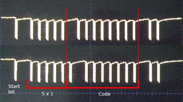
It would be easier for us to decode those signals, when we place them one over the other as follows:
The signal is transmitted from left to right. A starting bit is first to be transmitted. Then, 5 aces (5x1) follows the signal. From then on, 9 bits will follow, and those bits are considered to be the data bits. The last two bits should be the end bits.
According to what key we press, the transmitter will send this pattern, and the code bits shall change. The buttons that i chose to send are not random. I run some tests and saw that when the numeric keys are pressed, the code bits will have the binary number of each button.
In the first case, the top code has from left to right the following bits sent:
011111111
In the second case, the bottom code has from left to right the following bits sent:
101111111
The first (top) code was sent when we pressed the button 1, and the second code (bottom) was sent when we pressed key 2. If you mirror the binary numbers and invert the bits, you will get the number 1 and 2:
011111111 = 111111110 = 000000001 = number 1
101111111 = 111111101 = 000000010 = number 2
It should be taken into account that the delay from pulse to pulse, AKA period of the signal is approximately 1mSec. This is good to know for other projects, but for this project is irrelevant.
Now you should be able to predict the whole series of code that will be sent when we press number 4 of the transmitter.
Code sent when key 4 is pressed
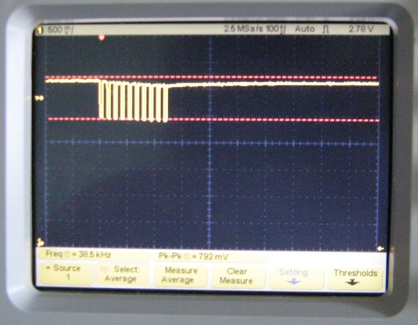
Back to the oscilloscope for a closer look. If you look the pulses driven to the LEDs closer, you may notice that they are not very clear rectangular pulses. That actually draw my attention and decided to press keys on the transmitter having a faster time base chosen on the oscilloscope. This would actually magnify the pulses. I chose a time division that would actually show one pulse to each screen. And here are the results!:
Each pulse when is magnified, it appears to be composed from several other pulses. Those pulses are actualy the carrier frequency of the remote control. In our case this carrier signal is about 38.5KHz. In general, remote controls have carrier waves from 25KHz to 45KHz. This carrier wave is used to distinguish pulses sent from the remote control from other random and ambient light. The receiver has a filter that will allow only frequencies near the carrier frequency to be driven to the decoder.
I hope i managed to explain in simple words how the remote control works. On with the remote signal jamming now!
How to make a remote control jammer
If you have already read the previous section on how remote controls work, you may have already understand the trick yourself. The goal is to confuse-blind the receiver. A simple way would be to place some non transparent tape over the IR receiver...dooooh. Ok, the idea is to confuse the receiver by sending a constant IR pulse with the carrier frequency of the transmitter. When someone tries for example to change a channel with the remote, the IR pulse from the transmitter will be combined with our pulses. The result will be a non-accepted signal from the receiver and therefore no action shall be taken. That's all.
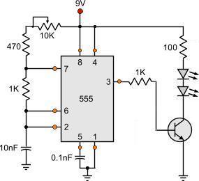
There are not much to say about the circuit. The 2N2222 transistor is used for switching the IR LEDs. It would be better to use 5mm LEDs. Any kind of IR LEDs would fit but you may need to change the 150 Ohms resistor accordingly.
The output pulses will have a frequency according to the RC circuit of the 555. This RC circuit is composed by the 1K resistor, the 10nF capacitor connected in series to the previous resistor, and the 10K potentiometer with he protective 560Ohms resistor.
If you use the 555 astable multivibrator calculator provided, you can calculate the min and max frequencies that this circuit can operate at. For the minimum frequency, the R1 should be considered as the sum of the 10K poti with the protective 470 Ohms resistor:
The remote control jammer circuit assembled on a bredboard
For the maximum frequency, the potentiometer is considered to be at it's lowest resistance and that would be 0 Ohms, therefore the R1 would be 560 Ohms:
R1 = 470 Ohms
R2 = 1000 Ohms
C = 10nF
F = 58421.11 Hz
The range is approximately from 11.5KHz to 58KHz, enough for almost every remote control on the market.
You could add optionally a switch in series with the power source. The voltage can climb up to 15 volts, but resistors that polarizes the transistor needs to be re-calculated. Use the LED resistor calculator from Dr.Calculus to calculate the 40 Ohm resistor.
Now, you can sit back and relax, watching your favorite TV show, without anyone being able to zap around the channels!
HI There, as a 60 year old Engineer (Mechanical)I read your article and most of it went over my head, however more to the point is that I started to understand how the signal process comes about.
To come to the point; I have a patent that requires voice activation of an LED screen displaying the spoken commands clearly in english. I can manually program a remote to gain the outcome that I want. IE. key in the words I want displayed and then push the "Go" button to display the message. However I need to just say one of the 7 commands and want the screen to display the message. Is this some thing that is a simple outcome or will it get messy and expensive...Hint!! If you have an inexpensive solution, I would be willing to share in the outcome of the product hitting the market...I have a global patent. John playground42@optusnet.com.au
@amalu friend, the correct frequency is the one that your remote control has, but i can totally assure you that if you get 39KHz on your jammer, it will work for anything between 37 and 40. You may need a frequency counter to see the frequency of the jammer. If this is not available as well, then you need to stay in front of your tv, play with the potentiometer and test.
Getting the vf of an LED is not easy. But this is something that you must know when you buy it. A typical VF is 3.2 volts. But IR LEDs may have 1.3 volts, because they are ment to be used in remote controls which they operate with 2 AA batteries. You need to ask the man you got them from.
At 13 August 2011, 14:29:51 user amalu wrote: [reply @ amalu]
thanks ,what i do to get correct frequency of my jammer? oscilloscope not in my hand? how i get the vf of led? what is the correct vf of the jammer?please help me
@amalu IR LED glow===bad news. Your LED is probably dead. The reason that i suspect is that you used a 1.3V LED instead of the 3.2V that i use. It got double the voltage it can handle. I did the very same mistake myself once, and the LED glowed (pale red) for its last time. So, you need to verify the forward voltage (Vf) of your LED and use the appropriate resistor instead of the 40 ohms that i use.
At 10 August 2011, 11:25:43 user amalu wrote: [reply @ amalu]
hi,i did this again and again ,but i didnt get a jammer,the ir led was glowed but i didnt gets its output i cant to jam my tv... ,so please help me to correct this work perfectly ,please tell me the corrct frequency of jammer and its time period pleaseeeeeeeeeeee
hi, this is shahid, i have all the components required and i wish to make thos circuit..but before that i wanted to know that '' is this circuit correct?? and if yes, why your IR LED is glowing?? because IR LED doesnt glows...
At 12 March 2011, 12:26:28 user Fung wrote: [reply @ Fung]
Emm...after testing, I think that BC546 may not be suitable because it generates heat with a maximum temperature of 32.5 degrees (background ~22 degrees), BC338 or even BC639 are more suitable.
Some receivers have an indicator to show that a signal is received from a remote control. Without finding the frequency of a remote control, if I found that the indicator blinks when I turn the variable resistor of this jammer, is that the remote control's frequency?
I find your work really interesting..i want to try it myself....Can you help me with the right component i should order that will be fit for this circuit. I have attached a link from a suppliers website ...can you pin point which component to chose
thanks
Hello shama. I am not quite sure that i have understand your question. You mean, why have i connect the oscilloscope? Well, the reason for the oscilloscope is NOT to make the remote control, but to see what kind of signal it sends, what is the frequency and what letter it transmits. If you ask something different, please rephrase your question.
this all things are ok but didn't got the conection exactly.means by connecting oscilloscope how can remot work? pleas, if possible discribe it. i will be grase full to you.
The circuit is an astable multivibrator with 555. Go to the section named "The simple TV remote control jammer circuit" above, and you will find all the theory needed to calculate it yourself, and an on-line calculator for this circuit.
ok..would you please send me the parts .. as i could not get the 2n222 they give me att2222 insted and they told me it is the same ...maybe that is where everything went wrong ...thanks again
I tried again and again,I checked the circuits for mistake all i noticed was \" that the current going through all a part from the last 2 Led,any clo whay is that ?
Badway i am sorry, we do not sell kits here, not yet anyway.
I can send you the parts needed, but it would be better for you to do it yourself, and i can help you with this as much as i can. Subscribe to our forum and post images of video links with what you have done, and i am sure we will find the error.
I done it all.. and it did not work .. as i done other on the net all did not work..it seems that i been doing something wrong.
any chance of sending me one done ?? i will pay for it.. thanks in advance
You can use an IR decoder chip along with it's equal IR encoder. You could use this chip (http://www.microchip.com/wwwproducts/Devices.aspx?dDocName=en010407) for example to do a pair.
To decode ANY signal from ANY remote control, you will need either a microcontroller or you can send the signal to a PC through the RS232 port for example.
I hope i covered you because i am not sure what exactly you meant with your question.

 Home
Home
 Projects
 Experiments
 Circuits
 Theory
 BLOG
BLOG
 PIC Tutorials
 Time for Science


 Contact
 Forum
Forum
 RSS
RSS


 Reddit this

