Worklog - I had this crazy idea yesterday morning! (Octomber 3 2010)
The lighting of the cover was good, but not good enough. Something was missing. I felt this "empt" feeling looking at it, and then suddenly, a crazy idea came to my! The cover will not be permanently lighted. Instead, it will be illuminated only when a button is pressed (or when the joystick is moved). And then i took it one step further: The cover will be permanently illuminated but with a very dim light, and when a button is pressed it will be illuminated with full brightness!
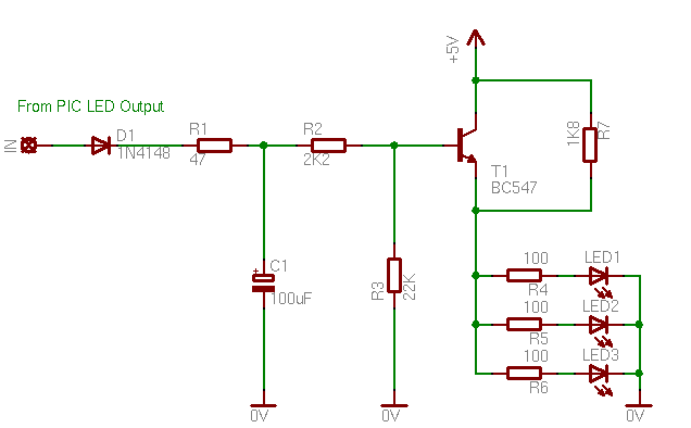
And then i took it another step forward! The cover will be permanently illuminated but with a very dim light, and when a button is pressed it will be illuminated with full brightness. When the button is released, the cover will slowly dim to the original "dimmed" state! I was so excited with this idea! For the dimming effect, i will use this LED Off Delay with dimming effect circuit that i made a couple of months ago, and frankly had no idea that i would use it in my MOW console. Here is the schematic diagram of the circuit, which is adapted to my needs:
The first change is the add of the D1 diode. That is because the original circuit was controlled by a switch that is ON or OFF, but this one is going to be controlled with a microcontroller output, which is high or low. The resistors R1 R2 and R3 are adapted to my needs, after testing with several different values. The last change is the add of the resistor R7. This resistor, will prevent the LEDs to be completely turned off, when the transistor is gone to cut-off area. R7 will allow a certain amount of current to pass through, and this will set the "dimmed brightness" of the LEDs. Once more, the value of this resistor came out of several tests.
So, here is the circuit mounted on the controller PCB (good i had this pre-drilled PCB, otherwise i had to re-make the PCB):
Well, "lol", as i always, say "Use all your abilities to win". After all, you can get yourself a customizable controller from the market. And then, i hope i meet you in the battlefield... preferably at the opposite team... ;) ;) ;)
PS: This is not cheating. I don't use a bot to do something that i can't, faster or more accurate. I mean, hey, be wise and gather all the shortcuts that you need close. You can do that. You can customize your shortcuts... You can use the shift key, the control, double clicks...Everything. Is this so hard to do? Or do you miss the LED effect that i have???
At 14 December 2010, 8:28:25 user lol wrote: [reply @ lol]
man you are such a nerd, go, get a wife children and a life.
with this frankenstein like thing you have clearly an unfair advantage
you super nerd hardwarecheater.
At 3 December 2010, 4:03:43 user Don wrote: [reply @ Don]
Oops! Just realized I was reading the comments in backwards chronology! My bad! Sorry, nevermind my last comment!
At 3 December 2010, 4:00:56 user Don wrote: [reply @ Don]
Just ran across your site! Thank you! Very informative! A note to Marc Leonhart (since nobody answered him; AND although I haven't studied all the specifics): I believe an input device like this could do anything you would like it to do. It is custom made. I'm sure it could be modified to any purpose!
Of course it can. But there are in the market remarkable shortcut consoles for this. You may be interested in this project, either if you want to DIY and for you the trip is more important than the destination, or because you want to do something that the market consoles wont do. In my case, i fit in both cases. The joystick for example is not just a normal arrow key replacement. Does much more that a normal game console cannot be programmed to do. But most of all, i just wanted to do it...
So can a project like this be fitted towards Photoshop and Sai, since I draw with the right I want shortcut keys for the left. But need more button option.

 Home
Home
 Projects
 Experiments
 Circuits
 Theory
 BLOG
BLOG
 PIC Tutorials
 Time for Science

 Contact
 Forum
Forum
 RSS
RSS


 Reddit this

