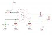
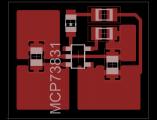
I have made a small pcb for my charger. I used very small packages (for my standards) and i was amazed by the final result. By the way i am gong to use them as long as i can, because you can reduce in an unbelievable way the size of your circuits....
The Schematic Diagram And The PCB Layout
 |
 |
| The schematic diagram of Li-Ion, Li-Po battery charger. |
The PCB of the Li-ion, Li-Po battery charger i made. |
The schematic and the board was taken by the MCP73831 datasheet. In the following files you can download the schematic and the pcb in eagle extension and of course the MCP73831 datasheet.
* IMPORTANT NOTE
When you open the board you will have to press the ratsnest button in orded to be filled the thermal pads i have made. Microchip also advise that we should use double sided PCB connected with vias as a result to increase the thermal pads and reduse the heat of the MCP73831 when charging the battery.
Choosing The Correct Resistor For Providing Desired Current
As we mentioned in the presentation tab the charging cycle of a Lithium cell begins with a "Preconditioning Mode"
(where it is also said as a trickle charge) after that enters the fast charge ("Constant Current mode") and then enters the final charging state which is the "Constant Voltage mode". PM -> CC -> CV
Depending on your needs and according to the selection of the MCP738** you are going to use, the "Preconditioning" and the "Constant Voltage mode" are fixed by the manufacturer. The only selection you will have to make is the RPROG resistor. The RPROG resistor sets the output current and it must be selected of 1C of the capacity of your battery.
Example:
If you want to charge a 500mah battery then you must charge it with a 500ma (max)
If you want to charge a 200mah battery the you must charge it with a 200ma (max)
and so on....
"This charging method is rated at 1C and it is safe to be used according to battery manufacturers."
The calculation formula is:
IREG = 1000v/RPROG
Where:
RPROG = kOhms
IREG = milliamperes
So if we select a 2KOhm resitor the output currect of the MCP would be IREG= 1000/2000= 500ma
***Where this output current is the maximum output current for this chip***
Status Output
When charging the battery cell the MCP has a pin (named STAT) where you can easily watch, in which state the charging cycle is. Below is the output state in each charging step.
Shutdown ------------------------> Hi-Z (High Impendance)
No Battery Present --------------> Hi-Z
Preconditioning ------------------> Low
Constant-Current Fast Charge ---> Low
Constant Voltage -----------------> Low
Charge Complete Standby -------> High
So you can use a single led as i did (see in schematic) and when the charging is complete the led goes off.
Tip !!!
You can use a bicolor led (red/green) and connected in a way that when charging to be the red led on and when it is completed the green to lit up.
Bill Of Materials
| | Resistors | | R1 | Smd(0805)Resistor 470 Ohm | | | RPROG | Smd(0805)*See text above | | | | Capacitors | | C1 | Ceramic Capacitor 4.7uf (You can also use electrolytic) | | | C2 | Ceramic Capacitor 4.7uf (You can also use electrolytic) | | | | IC | | IC1 | MCP73831 Single Cell Fully Integrated Li-Ion, Li-Polymer Charge Management Controller | | | | Misc | | LED1 | Smd (0805) Red Led | |
 Continue reading. Click here to view the presentation. Continue reading. Click here to view the presentation.
Comments
At 1 February 2016, 0:31:26 user mike wrote: [reply @ mike]I was unable to find suitable polarised connectors so instead I use three pin headers and sockets wired minus/plus/minus so it doesn't matter which way round you plug them in.
At 19 January 2016, 10:44:07 user Thien Nguyen wrote: [reply @ Thien Nguyen]Hello Panagiotis,
Your circuit is great. So, I really want to see a its schematic. However, I can't open that file. Can you upload it with pdf or send me file pdf?
Thank you very much!
At 10 September 2015, 9:57:19 user Ben wrote: [reply @ Ben]--Does this charger work for BOTH Li-ion AND Li-polymer cells?
Yes the MCP73831 works for both battery types.
At 7 February 2015, 13:53:59 user Panagiotis Kalogeris wrote: [reply @ Panagiotis Kalogeris]Hello Declan
Well I made one more mistake in my last post I wrote (Vcc). I should have written (Vdd) for common anode LEDs and the opposite for common cathode (Vcc). Also the rush schematic I did , it's not very clear (since text editor) if don't understand the way you should connect it I will upload a schematic to the page.
Regards Panagiotis
At 7 February 2015, 8:59:37 user Declan wrote: [reply @ Declan]Hi Panagiotis,
Many thanks for your advise.
I will try both options and let you know how I go.
Declan
ps. have a look at www.ecowatch.co.za
At 7 February 2015, 0:30:56 user Panagiotis Kalogeris wrote: [reply @ Panagiotis Kalogeris]And another way more easiest is to buy a bicolor common anode 3 pin led and connect the common anode to (Vcc) and the other two pins to Stat pin of the Mcp...
Regards Sorry for the multiple answers...
At 7 February 2015, 0:23:11 user Panagiotis Kalogeris wrote: [reply @ Panagiotis Kalogeris]Forgive me i missed something critical......
You will also have to connect another one resistor to ground....
stat pin----------bicolorled----- ----------resistor Vdd
|----------resostor Vcc
Hope to understand.
Panagiotis
At 7 February 2015, 0:10:33 user Panagiotis Kalogeris wrote: [reply @ Panagiotis Kalogeris]Hello Declan
You dont need any more schematics to achieve your goal.
Just buy a bicolor led with 2 pins (not 3) and connect it as the led in the schematic.
Advise the status output of the mcp where can be found in the worklog tab in order to see how to connect it according the output and your desire.
ATTENTION>>>> This trick works only with MCP73831 not MCP832
If you have any more questions feel free to ask again
Panagiotis
At 4 February 2015, 19:39:00 user Declan wrote: [reply @ Declan]Great post - I used it and have built a charger that works great.
How would I connect a bi-color LED?
Please could you show me a circuit?
many thanks
At 15 September 2014, 10:19:36 user computerman wrote: [reply @ computerman]Hello Allan,
I have a question.
I have 1 cell with this specification 3.7V 2000mAh.
Did i say it write that i can use a 2K resistor and than the batterij is full in 4 hours.
Please let me now.
many thanks.
computerman
At 15 September 2013, 7:13:26 user Panagiotis Kalogeris wrote: [reply @ Panagiotis Kalogeris]Hello Allan. The connectors i used are very common in an electronic shop.I found them as "polarized headers" and i think that their designation is due to the fact that you can't place them in an opposite direction.
Most electronic shops have them in their showcase.
Now...If you look in the datasheet of the chip says that it can be used for BOTH TYPE batteries. But my friend beware and charge them in a rated current of 1C!!!Look my worklog section for more info.
***ALSO THIS CHARGER IS MEANT TO CHARGE ONE CELL ONLY!!!!!!!***
At 5 September 2013, 17:59:56 user Allan wrote: [reply @ Allan]Thank you, Panagiotis, for taking time to share your work.
What two-conductor connectors did Panagiotis use to connect/disconnect the cell? Does this charger work for BOTH Li-ion AND Li-polymer cells? |
|
 HOT in heaven! HOT in heaven!

|
|

 Home
Home
 Projects
 Experiments
 Circuits
 Theory
 BLOG
BLOG
 PIC Tutorials
 Time for Science
 Continue reading. Click here to view the presentation.
 Contact
 Forum
Forum
 Projects
 Experiments
 Circuits
 Theory
 BLOG
BLOG
 PIC Tutorials
 Time for Science
 RSS
RSS