
|
 Home Home
 Projects Projects
 Experiments Experiments
 Circuits Circuits
 Theory Theory
 BLOG BLOG
 PIC Tutorials PIC Tutorials
 Time for Science Time for Science
|
| ||
|
22 March 2009 Author: Giorgos Lazaridis Connecting CapacitorsConnecting capacitors in series A series connection of capacitors is when the end of one capacitor is connected to the start of the next capacitors. If the capacitors are electrolytic capacitor, extra care should be taken with the polarity. The + wire of the first capacitor must be connected to the - wire of the next one, like when connecting batteries in series: 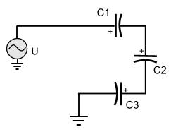
The total capacitance in series connection When connecting capacitors in series, the total capacitance is calculated from the following series:
In special cases where only 2 capacitors are connected in series, there is an easier way to calculate the total capacitance using the following formula:
As can be seen above, the more capacitors you connect in series, the less the total capacitance becomes. In general, the total capacitance will finally be less than the the capacitor with the less capacitance. The total impedance in series connection The formula to calculate the impedance of one capacitor connected to an AC power source is:
The more the capacitors in a series connection, the less the total capacitance becomes. Thus, the more the capacitors in a series connection, the more the impedance of the series. The voltage drop in series connection Same as when connecting resistors in series, the sum of voltage drops across each capacitor equals to the voltage across the whole series: 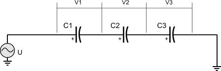
U = V1 + V2 + V3 in general: UTOTAL = VC1 + VC2 + ... + VCn The voltage drop across each of the capacitors is given from the formula:
Where QTOTAL is the total charge of the wjole circuit and is calculated from the formla: QTOTAL = CTOTAL x U Connecting capacitors in parallel A parallel connection for capacitors is when all capacitors in the circuit have common starts and ends. Special care should be taken when electrolytic capacitors are connected in parallel. Their wires should be connected in respect to their polarity. All wires with + polarity should be connected together: 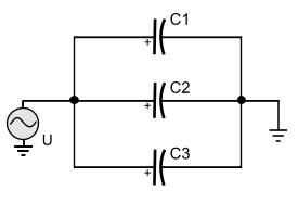
The total capacitance in parallel connection The total capacitance in a parallel connection for capacitors is the sum of all capacitances within the circuit: CTOTAL = C1 + C2 + ... + Cn As can be seen from the above formula, the more the capacitors in a parallel connection circuit, the more the total capacitance of this circuit. The total impedance in parallel connection The formula to calculate the impedance of one capacitor connected to an AC power source is:
The more the capacitors in a parallel connection, the more the total capacitance becomes. Thus, the more the capacitors in a parallel connection, the less the impedance of the series. The voltage drop in parallel connection In a parallel connection of capacitors, same as in parallel connection of resistors, the voltage drop across each part of the circuit is the same as the total voltage U. Thus, if U=10Volts, each capacitor will have 10Volts across it's leads. Relative pages Comments
|
|
 Contact Contact
 Forum
Projects
Experiments
Circuits
Theory
BLOG
PIC Tutorials
Time for Science Forum
Projects
Experiments
Circuits
Theory
BLOG
PIC Tutorials
Time for Science
 RSS RSS
Site design: Giorgos Lazaridis © Copyright 2008 Please read the Terms of services and the Privacy policy |


 Reddit this

