In the following article, i explain the principles of operation of a brushed DC motor with permanent magnets. Also i show how a DC motor (with permanent magnets) is made and what is inside in such a motor. If you are interested in brushless DC motors, then better go to the page about how brushless DC motors work.
The Ampere's rule (the right-hand screw rule)
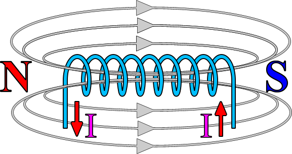
It is Frenchman Andre-Marie Ampere (1775-1836), a mathematician and physicist, who discovered what happens to a wire winded in a coil when current flows within. The current will generate a magnetic field around the coil, as shown in the following drawing:
The "right-hand screw rule"
Using your right hand, you can find out the direction of the magnetic lines as well as the North pole orientation. Close your fist and hold your thumb upwards, like thumbs-up. If you had the coil inside your hand and your fingers (except the thumb) was showing the direction of the current, then the thumb shows the direction of the magnetic lines as well as the orientation of the North pole. This is called "the right-hand screw rule".
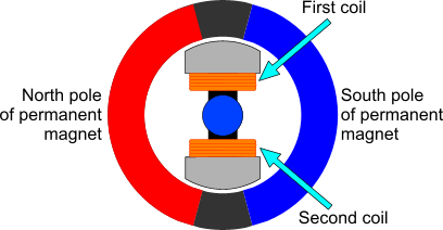
The basic DC motor has actually two windings and two permanent magnets. The coils are powered from the commutator and the brushes. We will see these two later on. For now, you only need to know that during a full cycle of the rotor, the current that runs through each winding change direction once. Thus, each electromagnet will change its magnetic polarity. Moreover, the windings of the two magnets are winded in reversed direction. Thus, when one electromagnet is North, the other is South and vice versa. Look at the following drawing of the basic DC motor:
The following animation indicates how the two electromagnets changes magnetic polarity during a full rotation:
I have with RED color the North pole and with BLUE the South pole. If you watch this animation, you will see that there is one moment that both electromagnets are turned off. This is the time that the basic DC motor provides no torque at all. In all other occasions, the magnets are either PULLED from the opposite pole or PUSHED from the same pole and therefore the mechanical power is generated.
The commutator and the brushes of a DC motor
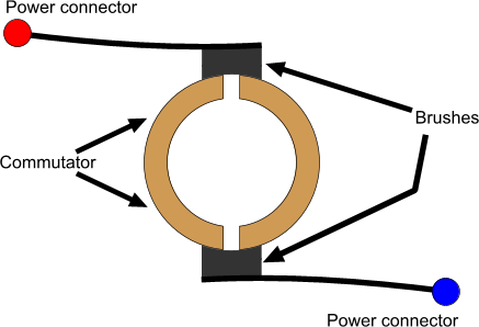
This kind of DC motor is called "Brushed DC motor". Why? Because it uses brushes... The brushes are the way that the motor provides the coils with power, and the geometrical characteristics and position of the brushes (and the commutator of course) will be responsible for changing the magnetic field of the two electromagnets according to the position of the rotor. So, how this is done? The brushes are two metallic pieces that act like springs. On one side, they have a piece of conductive material, usually made of carbon to stand against friction. On the other side, they have the pin that the power supply is applied to the motor. The brushes are pushed (by the spring action of the metallic part) against the commutator. The commutator is a metallic ring, also conductive and able to stand friction, that is divided in two parts. The following drawing explains how these parts are:
The commutator is fixed on the shaft of the motor. Each semi-ring has one pole of each coil. Giving thus power to both half-rings, is like giving power to the coils. But while the shaft of the motor rotates, the commutator rotates as well. This causes the poles of the power supply provided to the coils to change. This change of the electric poles, has an affect on the magnetic poles as well. The current direction is changed and - due to the rule of the right-hand screw - the poles of the electromagnets will also change. The following two animations indicates this procedure. The left one shows the brushes and the commutator from above, while the right one shows how the electric and magnetic polarity is changed.
Notice how each part of the commutator changes polarity as it rotates. This is the basic operation of the DC motor. Notice also, that there is one moment that the commutator is short-circuited. During this time, the motor produces no power at all, and also the short-circuit can cause several damages due to over current. This of course does not happen in real life. Later on, i will explain how this is avoided. Now, its worth to see this video that explains exactly how the DC motor is made:
Real life is different
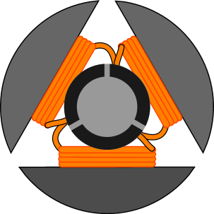
This is a schematic drawing of the coil arrangement of a real motor.
Indeed it is. Nevertheless, the theory of operation is absolutely the same as above. What changes is the number of coils. Instead of 2, there are actually 3 coils that takes part. These 3 coils will solve the following 3 problems: First of all, there is no more this position that the commutators are short-circuited, and the motor will provide all the time torque, without the problems from over-current. Also, while in operation, always two or three coils will be active and interact with the permanent magnets. And because the coils have 120o angle between them, the torque provided by the motor is much more smooth and never falls to 0. Finally, if the motor had 2 coils and it was stopped in this position where the commutator is short-circuited, it would be impossible to start it again.
Of course, the 3 coils require now a different construction of the commutator. It is composed by 3 pieces instead of two, and the gaps are in circular pastern with 120o angle. The brushes are again two. The following animation shows how the real motor with the 3 coils works:
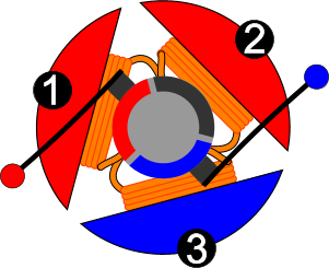
The way that the armature changes magnetic polarity is not that easy to understand as in the simple motor with 2 electromagnets. To understand the operation, you need to know first of all how the electromagnets are internally connected. The following image indicates this connection:
All electromagnets are winded with the same direction of rotation. Now, we have to distinguish two different situations as the motor rotates, The first situation, is when a brush is between two collectors. At this moment, all collectors are having power. During this time, one coil will have the same polarity between its poles, thus, this coil will NOT produce a magnetic a field as no current flows within.
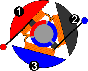
The other situation is when one commutator piece has no power. This happens most of the time during the rotation of the motor. This commutator piece will act as a bridge for the two coils, that have one wire connected on it. Thus, these two coils will be considered as connected in series! And because their windings -as said before- have the same direction, they will both produce a magnetic field of the same magnetic polarity. The following two images indicates these two situations.
The piece of commutator that is black has no power. It acts like a bridge for coils 1 and 2. These coils are connected in series and they generate the same magnetic polarity.
All commutators have power. This time, coil 2 has both its ends to the same electric polarity - NEGATIVE. Thus, coil 2 will produce no magnetic field at all.
Finally, let's see a real motor hos it is made!
I always like tearing things apart and see how they work!
The victim
An exploded view of a DC motor. You can see the stator the rotor and the cover
Inside the stator you can see the two permanent magnets, one opposite the other.
A close look on the rotor. The 3 electromagnets (armature) can be seen. Also, you can see the commutator, and -if you look close enough- you will see the gap between the contacts of the commutator.
This is the cover from the inside. The brushes are fixed on the cover. The spring-action metal along with the brushes are visible. On the other side of each metal there is the power contacts of the motor. They go out of the cover
Look close enough and you will see how the brushes are pushed against the commutator contacts.
@Kazi the spring must be able to provide enough tension and the brushes must have enough material to make contact. that's all you need to check. Bad brushes can cause problems for sure.
At 20 February 2015, 4:13:30 user Kazi wrote: [reply @ Kazi]
How do I know when to change the brushes in a DC treadmill motor? I notice a burning smell when I use my treadmill accompanied by a brief burst of higher speed. Could this be due to worn brushes?
thanks
At 11 January 2015, 14:19:25 user malu wrote: [reply @ malu]
Why can't you increase V at max free spin to raise RPM, I hence EI and output ongoing? ( BDCM obeys V = E IR )
Is this due to saturation of electromagnetic poles?
First at all, tks your explanation so much!
But i am wondering with question?
some DC Motor has an extra housing although it already had a housing as your video
What is the purpose of this extra housing???
Traditionally, the Lorentz force is used to explain the force on the motor's armature. Your explanation uses the attraction between the field magnets and the armature as it's considered to be an electro-magnet. Do you consider this to be equivalent to the Lorentz force, and if so how?
Sirs:
Under your 'DC Motor' page and then under the heading, 'Ampere's rule' you talk about the "Right Hand Rule"
The correct rule is the 'Left Hand Rule'.
From 'Understanding Radio' copyright 1941, 1951, 1960 by McGraw-Hill Book Company. Authors: Herbert M. Watson, Herbert E. Welch and George S. Eby.
The reference 'Left Hand Rule' is stated in the 1960 copyrighted publication; Chapter 4, page 59, 'Magnetism and Direct-Current Meters', "How is the left-hand rule used?".
The Left Hand Rule is also addressed in many other publications about motors, electronics.
@marc What type of motor is that? AC squirrel cage?
At 19 August 2013, 0:26:31 user Roger wrote: [reply @ Roger]
What is the relationship between lenght of the motor and components and the diameter?
At 12 August 2013, 19:58:29 user marc wrote: [reply @ marc]
@Giorgos Lazaridis i wanted to see if you could help us troubleshoot something, we're working on a project our goal was to build a clear dc motor. we took apart a new starter motor from a car and had a piece lexan tube machined to the same specs as the original motor casing but when assembled and bench tested the motor it dosent opperate smoothly. it sounds as if the timing is off, if the electro magnet fields are off slightly will it cause this? thank you for any help you can offer
@Zach this depends on the direction that the coils are winded. The point is that -whatever the current direction or coil- there must be a south and a north pole.
At 9 June 2013, 18:37:48 user Zach wrote: [reply @ Zach]
Hello, Thank you for the great video and explanation on dc brush motors. However, I did have one question regarding the direction of the current. In regard to the two coiled motor you used in the video,would the current be going in the same direction for both coils thus making the north and south poles for both coils be in the same direction?
I am facing one problem there are six wires in one dc motor. Iwant to change the direction normaly i try to change the armature connection then no more change in direction. How can i change the direction pl. give a good sugestion. thank you.
Well, I don't know about this. It was hard for me to follow. What would be more explanatory to me would be for a sine wave super-imposed onto the brushes because this is where the AC is applied to the "commutator". Because of the change in magnetic poles due to the alternating current through the brushes it creates a "repelling(north vs north and south vs south) and attracting(north vs south or south vs north)" characteristic of magnetism which then causes electromagnetic induction onto the coil in the rotor only to then be applied against the stator (permanent magnet of motor which is aligned to be the opposite) to again create the opposite poles and thus turns rotor to continue the movement. A change in AC voltage to the commutator will dictate the RPM of the rotor. The lower the voltage the slower the rotor. So what is happening is that three phase current (basically north vs north OR south vs south happens three times a cycle or 180 times per second) is changed into DC thus continuous movement of rotor. Once again for all this to be understood you need to compare the position of of the rotor to the sine waves of the incoming AC current which in most cases is going to be three phase.
@Sumeet Pahw
Hi I think I have absorbed all you have had to say on 3 pole electric motors howsoever I am slightly confused on magnetism as I am at the happy age of 72 a railway modeler and I find that my best running engines definitely go best when they are fitted with 5 pole motors.
Now the question please: I believe that a 5 pole motor can run within the same field coil as a 3 pole. If this is true how is that please? Else: how are five differing magnetic fields produced in 360 degrees from a circular magnet; an even number I might just understand but an odd number doesn't seem conducive to conservativeness field production.
Hope you can help me,
H Chris Spreckley.
England.
can someone help.. Why a DC motor has a commutator and not slip rings.
and someone post the aswer in commments.. thanks
At 15 November 2012, 7:19:04 user Jeff wrote: [reply @ Jeff]
Very clear explanation.
Thank you very much for making this.
At 10 November 2012, 19:52:24 user Gauta wrote: [reply @ Gauta]
Hey guys I'm artisan electrician I would like to know futher about DC machines thanks
At 22 October 2012, 15:42:28 user Negg wrote: [reply @ Negg]
Graphics used and the video made me understand everything completely. I spent 10 minutes surfing the web and this tutorial was the best I could find on brushed DC motors. Wonderful job! Thanks!
At 29 September 2012, 11:20:23 user priya wrote: [reply @ priya]
fantastic job sir. its very clearly understood by me and i had read about the realys in the same website 2 months ago really its fantastic that i did not forget. i dnt have much memory power bt it feels so swet thst i can remember by seeing pics n videios explained in this manner. thnk you so much for providing such a great website fot the students like us
At 26 September 2012, 22:55:55 user Ricardo wrote: [reply @ Ricardo]
I love you so much!!! this is the best description of how a stepper motor works that i have seen ! thank you for everything!
@Shane what really matters is to have the proper magnetic polarity. so, either the coils are winded as you said, or the coils have the same winding direction but different current polarity.
At 17 September 2012, 13:20:45 user Shane wrote: [reply @ Shane]
Hey just wondering, for your two pole motor, are both coils wound the same way or is one clockwise and the other anticlockwise? Cheers
@Concy normally, the energy that the motor will get from the permanent magnet during impulsion will be the same during attraction, so the total E will be zero... But i cannot tell for sure.
At 2 August 2012, 15:43:04 user Concy wrote: [reply @ Concy]
@Giorgos Lazaridis
It is possible to actually create a motor using permanent magnets?
I have seen videos people using cpu fan and permanent magnets are working. Is it real or fake.
http://www.youtube.com/watch?v=7PDeK6rprA4&feature=related
@Rajesh because we either need a rotating or a switching magnetic field. Nevertheless, there are many people who tried to make a motor only with permanent magnets
I hope i'm not complicating things., But you see electric field creates flux around the winding, which forms concentric loops ,UNLIKE magnetic flux which gets from Point to point i.e NOrth to south. Thus this Interaction; i.e The straight flux(magnetic)while passing from North to Souch PUshes This circular moving(concentric) flux Along the way, creating a rotating force(Torque) which inturn rotates the coil..
@rohan mukherjee when current flows in a wire, it creates magnetic field. The only interraction between electromagnets and permanent magnets is the magnetic repulsion/impulse, but this is due to the current that flows within the electromagnets.
ok electromagnets have that amazing prop of changing magnetic pole directions.but tell me is the rotation only due to magnetic attraction and repulsion or due to currents in magnetic field..pls email me..nebdy..
thnx a lot..helped a lot..bt how electromagnets and permanent magnet magnet interact yielding force in aniclock or clock direction was not clear. But understood the general principle of permanent magnet and line current and force associated with that. also was not clear why use electromagnets ??
At 16 September 2011, 8:31:11 user Maddy wrote: [reply @ Maddy]
pls make some animation for the The Ampere's rule (the right-hand screw rule) and show the flow of current and force acting .
Don´t worry about your accent . It´s ok . If somebody puts you down about that .I wonder how he or she would speak a foreign language . Anyway good job chap , keep going , your explanation is very clear . thanks a lot ..............
Just awesome! Watched all youtube clips about it!! It was easy to understand everything from practical point! Thank you GJ!
At 16 February 2011, 4:03:17 user muqtar wrote: [reply @ muqtar]
Great ! I cant express how good u r at this,u have done an excellent job.a vry practical way of teaching.Thanks a lot.May ALLAH bless u..
At 28 January 2011, 19:51:25 user rock wrote: [reply @ rock]
I thank God for appointing you as an excellent teacher. I need not search for so many other websites. Even a child can very well learn by your teaching without any doubt. I feel as if i am attending real class room. your really very much talented and let your talent be recogonised by the entire world. I expect more and more from you on different kinds subjects. May God bless you with long life. Hats off to you. warm regards.
very very attractive way of teaching... This is my first visit to this site.. and I say it\'s wonderful... The way of interaction is perfect... I beg you please go along in this fashion and provide us knowledge through practical experience.. Indeed, I would vote this site as my favorite site..Thankssss....
thank you sirrrrr....cann''''t expect more from this explanation...fabulous...keep it up
At 14 October 2010, 19:24:01 user cory wrote: [reply @ cory]
i need to no how to build a fast 6 pole motor any one can help i would love u long time cuzz i am building a bendini g-field generator i can help u build one of them if you would like
Marvelous work. I am personally grateful to you for explaining a complex machinery in such a simple manner. Thanks again
At 16 July 2010, 19:12:39 user Greg wrote: [reply @ Greg]
Very thorough explanation, drawings and animations.
At 9 June 2010, 18:34:24 user ben wrote: [reply @ ben]
thanks
At 7 April 2010, 23:14:17 user Stu wrote: [reply @ Stu]
Using computer animations like you did, along with clear narration, is a really great way to explain how these things go together!
Awesome work and thanks so much for so clearly explaining something I\'ve been mystified by for a long while!
And I didn\'t think your accent spoiled anything, you\'re quite understandable.
Thank you!

 Home
Home
 Projects
 Experiments
 Circuits
 Theory
 BLOG
BLOG
 PIC Tutorials
 Time for Science


 Contact
 Forum
Forum
 RSS
RSS


 Reddit this

