|
27 June 2010 Author: Giorgos Lazaridis How a Key Matrix Work
 A typical PC keyboard with 109 keys A typical PC keyboard with 109 keys This is all the PCB that hides inside a keyboard. Only 26 connectors are used to interface all 109 keys! Thanks to the matrices. This is all the PCB that hides inside a keyboard. Only 26 connectors are used to interface all 109 keys! Thanks to the matrices.What you probably have in front of you, is a keyboard with more than 100 keys on it... If you are not familiar with the key matrices, then you may think that inside this keyboard, there is a chip (probably a microcontroller) that has at least the same number of inputs to read each key separately. Well, this is far from true...
What are the key matrices?
The matrices are actually an interface technique. It can be used to interface inputs like the PC keyboard keys, but also to control multiple outputs like LEDs. According to this technique, the I/O are divided into two sections: the columns and the rows. You can imagine a matrix as an excel sheet. Here is a 4 x 4 matrix
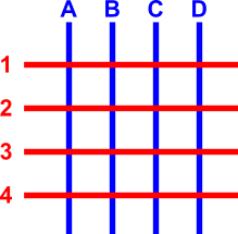
The blue lines are the columns and the red lines the rows. There are 16 knots that the rows and columns intersect. The columns and the rows are NOT in contact! Suppose that we want to make a key matrix. To do this, we will have to connect a button to each knot. The buttons will have a push-to-make contact. When the operator pushes this button, it will connect the column and the row that it corresponds to. Now i will put the push-to-make buttons onto the matrix
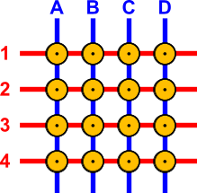
The buttons are named with the Column:Row name that they connect. For example, the top-left button is named A1 and the bottom right is named D4.
How does a key-matrix works?
To understand the operation principle, i will re-draw the above matrix without colors. I will also put connection pins to each row and column wire. Then, i will give power to only one column, the column B. The wire that is red, indicates that it has power, and the button that is purple indicates that the button is pressed. Then, i will simulate a button press to button number B3:
Watch the above animation. The column wire B has power all the time. No other wire has power, until the button B3 is pressed. This button makes contact between the column B and the row 3. Because column B has power, the row 3 will also have power as long as the button B3 is pressed! What this means it that, if we know which column has currently power, and we watch the rows, then we can understand which button was pressed, if we detect power on a row! If for example we know that the column B has power, and we detect also power to row 3, then we understand that the button B3 is pressed.
A matrix in the real life
So, how does a matrix finally works? If you have understand the previous example, then it will be very easy for you to follow. The matrix is controlled by a microcontroller. For the above 16-button 4x4 matrix, 8 pins of the micro controller will be used. The first 4 pins will be OUTPUTS and will be connected to the COLUMN wires, while the other 4 pins will be INPUTS and will be connected to the ROW wires. The OUTPUTS of the microcontroller will NOT all have power at the same time. The outputs will go high one by one in cycle. This happens many times per second, but i will slow things down...
So,this is -in VERY VERY slow motion- how a typical microcontroller would cycle its outputs. During this time, it will also monitor the inputs for a signal. As long as all inputs are LOW (with a pull down resistor or with internal uC pull-down resistors), the uC will take no action. Now, suppose that the operator presses the button 3C. Look what happens:
The microcontroller loops its outputs normally. The operator has pressed the C3 button. This button has connect the matrix col C, with the matrix row 3. When the output C of the microcontroller becomes HIGH, the signal arrives also at the input 3 of the microcontroller, through the pressed button. The uC monitors the 4 inputs and detects that when the specific output (C) is high, there is a HIGH signal at the input 3. So, this means that the input C3 is pressed! Easy it is not?
Pressing multiple buttons on a matrix
Pressing multiple buttons simultaneously on a matrix is not always a good idea. There are situations that the matrix operates normally, but not always. Suppose for example that someone pressed the buttons B1, B2 and B3 simultaneously. What will happen? Let's take a look:
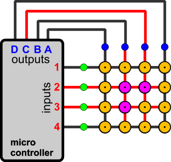
When the output B becomes HIGH, then the three inputs 1,2 and 3 of the microcontroller will also become HIGH. Supposing that the firmware is written in a way that can handle such an event, the operation will be carried out normally. The uC will understand that the buttons B1, B2 and B3 are pressed. Let's see another situation where the buttons A3, B3 and C3 are pressed:
In this situation, the matrix will also work normally. The microcontroller will detect a signal at input number 3, when the output A, B and C are HIGH. When the output D is HIGH, no signal is detected.
The ghosting problem
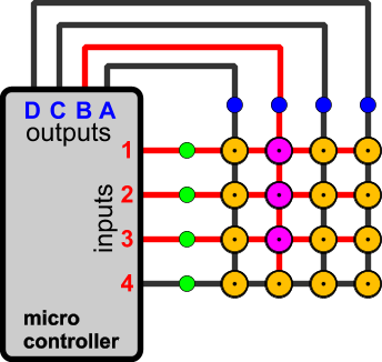
I will continue the above examples with another situation, where the buttons C2, B2 and B3 are pressed simultaneously:
When the output C is HIGH, then the input 2 will also become HIGH. The uC will understand that the button C2 is pressed. But something else happens here. The button B2 is also pressed! This means that the HIGH signal will go through the button B2 to the column B. And due to the fact that the button B3 is pressed, the signal will arrive simultaneously at input #3 as well! But the microcontroller knows that at this moment, only the output C is HIGH, and because it detects HIGH signal at inputs 2 and 3, it will think that buttons C2 and C3 are pressed, something that is wrong! The button C3 is NOT actually pressed! This is known as ghosting, and usually gives a headache to PC gamers, especially when the game requires multiple buttons to be pressed simultaneously. Take for example the MAME console, which simulates arcade games. If you play samurai shodown 1v1, and one player has low defense and kicks while the other is flying high and uses the sword, this will require 6 keys to be pressed! Yawks! Ghosting occurs. (that's why i made my MAME arcade console)
The masking problem
P]The masking problem comes in continue to the ghosting. When masking is occurred, the controller cannot detect a key change that has occur. Suppose for example that the ghosting problem has occur, by pressing C2, B2 and B3 simultaneously, like the previous example. The controller will think that the button C2 C3 is pressed, although the operator has not pressed C3. Now, the operator presses the button C3 without releasing any other button. Nothing changes at the microcontroller. And now the operator releases the button C2... What happens? Nothing! The microcontroller still thinks that C2 is pressed and cannot detect the button release! This is the masking problem, also a gamers headache.[/P]
 |
 |
 |
| By pressing buttons C2, B2 and B3 simultaneously, the ghosting problem occurs. |
The operator presses button C3, yet nothing changes |
Now the operator releases button C2. Still nothing changes and the uC cannot detect the button release! Masking has occur. |
Any solution to the ghosting and masking?
Yes there is! And it is a cheap one. Using a diode for each button, the masking and ghosting problems are instantly solved! This is how it works:
The above situation would normally cause ghosting. Yet, the diodes prevents the current to go backwards. For better understanding, you can see the 3 steps of the above animation here (as always, click to enlarge images):
Because the cycling speed must be quite fast (some Khz), you should choose proper diodes. A cheap solution is the 1N4148 general purpose diodes. If you plan to have many keys and thus you need faster sampling, then select a schottkey diode instead.
And what about a matrix with outputs instead of inputs?
This is also a very interesting chapter with matrices. Using matrices, you can control for example 9 LEDs each one separately, with only 6 outputs. Look how it works:
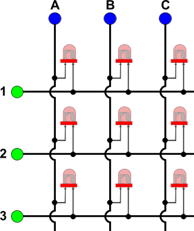
Above there is a typical 3 x 3 LED matrix. All microcontroller pins, for both columns and rows are now OUTPUTS. Suppose now that all outputs are HIGH. All LEDs will have HIGH on both anode and cathode, and this means than none LED will light! This is how to turn completely off the LED matrix, by giving either HIGH or LOW to all outputs. Now suppose that we want to turn on the middle LED. To do this, we give HIGH to column 2 and rows 1 and 3, and LOW to column 1 and 3 and row 2. This is what will happen:
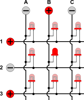
The middle LED is forward biased and therefore it lights. All other LEDs are either reverse biased, or they have the same voltage (positive or negative) to their both leads, and therefore they do not light. This way, someone can control for example 64 LEDs each one separately, with an 8x8 matrix, using only 16 outputs from a microcontroller.
Comments
At 16 February 2016, 13:01:57 user nagavikas wrote: [reply @ nagavikas]thanks for what a neat presentation,
can u send me the proteus and hex file for above project...?
and plz send me the related file too that would be more helpful to me
thank you in advance.........................!!!!!!1
At 3 December 2015, 8:19:32 user Ben Zuniga wrote: [reply @ Ben Zuniga]@Andy I wouldn't think you would need to turn a keyboard like that into a matrix, unless you mean you are customizing the keyboard to be a custom input device for something other than a computer.
At 2 December 2015, 8:07:27 user Andy wrote: [reply @ Andy]Thanks for a very clear and simple explanation. Been looking at getting an Ergodox but not quite satisfied with the design so I'm planning on converting my Razer Blackwidow into a matrix keyboard.
At 1 October 2015, 8:35:05 user Giorgos Lazaridis wrote: [reply @ Giorgos Lazaridis]@Vladimir for a 2x2 matrix you will need 4 wires to control 4 buttons, so why bother with a matrix and not just interface the buttons directly?
At 16 September 2015, 15:54:40 user Vladimir wrote: [reply @ Vladimir]What about 2x2 buttons grid? With Arduino and default buttons it does not work. (or may be i do something wrong). Please help
At 29 August 2015, 20:05:24 user Cris wrote: [reply @ Cris]Well, just realized that was a stupid question.....
At 29 August 2015, 19:59:28 user Cris wrote: [reply @ Cris]Hey and why don't they just make one row with all the 128 keys? you just have to divide a second into 128 parts... A 10mhz controller should do the job....
At 23 July 2015, 11:37:41 user Nandakumar wrote: [reply @ Nandakumar]Thanks for the good and clear article.
At 27 June 2015, 4:24:40 user paulsin wrote: [reply @ paulsin]I have made a simple technique to connect an 4*4 button pad to arduino using four digital pins of arduino instead of 8. Read more at :
http://www.haberocean.com/2015/05/circuit-for-44-button-keypad-using-74165-and-74595-part-1/
At 22 February 2015, 23:17:41 user okti wrote: [reply @ okti]Hello,
I have a keypad with this algorithm working very well.The next step in my project is to test if my code is working well without the keypad.I need to simulate my keypad and to test all the combinations for the keypad using 2 microcontrollers.Do you know how can I do this step?
At 9 January 2015, 14:09:36 user mike wrote: [reply @ mike]thanks, I was trying to wrap my mind around avoiding using the analog inputs, but I don't think it's possible. very good article.
At 22 July 2014, 16:12:48 user Giorgos wrote: [reply @ Giorgos]@ledforever You can't turn them on simultaneous. This is how multiplexing works. You turn them on for a period one after the other. The eye cannot catch the on-off delay.
At 22 July 2014, 11:00:02 user ledforever wrote: [reply @ ledforever]I didn't understand soemthing.
what if I want to turn on only 3leds . a1,c1 and b2 ?
At 4 April 2014, 0:06:48 user Edgar wrote: [reply @ Edgar]Very nice explanation, really a good work!
At 4 February 2014, 23:50:10 user Ben Zuniga wrote: [reply @ Ben Zuniga]@Grotty
From my fix with the Teensyduino with the same feature, this will not work. This is because the voltage on the pin needs to be driven down to around .7 volt to register as a low active. the pull up resister is very large and therefore have a man sum of the voltage drop from 5 to 0, undepowering the diode preventing it from cunducting, and if it did, assuming a silicon diode then you would get .7 volts and this could be read like static because of how close to the active zone, it is within drifting room.
At 2 February 2014, 9:25:09 user Giorgos Lazaridis wrote: [reply @ Giorgos Lazaridis]@Grotty the inputs are always pulled H or L to work properly, otherwise the uC input will float
At 30 January 2014, 20:29:39 user HARIKRISHNAN V wrote: [reply @ HARIKRISHNAN V]Simply and intelligently done. Great work!
At 23 January 2014, 16:05:08 user aravind wrote: [reply @ aravind]Simplified and superb Explanation.
At 16 January 2014, 4:21:49 user Grotty wrote: [reply @ Grotty]This is really good. Thank-you for publishing it!
One question though; will the diode fix for ghosting work when the inputs use pull-up resistors (as the arduinos do nowadays) simply by switching direction of the diodes and using a 0v output as the "active" line?
(Alas I don't have the kit to test this, and don't want to end up wasting money)
At 1 January 2014, 2:44:23 user Ben Zuniga wrote: [reply @ Ben Zuniga]This is great!
I was Having a ghosting problem, But this helped greatly, Thank You!
At 16 August 2013, 8:06:32 user Lefteris wrote: [reply @ Lefteris]Very nice article. Keep inspiring!
At 11 July 2013, 20:45:53 user Jordan wrote: [reply @ Jordan]Thanks for this! Key matrices and LED matricies were super confusing to me until now.
At 24 June 2013, 0:25:28 user muttonsandwich wrote: [reply @ muttonsandwich]I've been trying to understand this concept for ages! Thanks man!
At 6 June 2013, 16:44:00 user roopa jayvardhan wrote: [reply @ roopa jayvardhan]clear explanation easy to understand its nice & thanx
At 26 May 2013, 4:20:27 user sameera wrote: [reply @ sameera]
At 26 April 2013, 2:31:45 user khan wrote: [reply @ khan]good work ...really very nice explanation ....keep it up:)
At 11 April 2013, 20:33:58 user John McGeorge wrote: [reply @ John McGeorge]How can I make the down arrow and c on old keyboard work together.Thanks
At 5 April 2013, 17:42:26 user Kalpesh Wani wrote: [reply @ Kalpesh Wani]@nikhilr57 : Hi Nikhil , even I am working on similar chessboard. If u want to share ur experience/ want some input from my side, contact me on kalpeshswani@gmail.com
At 18 February 2013, 9:58:57 user Prince wrote: [reply @ Prince]Thanks for this nice article
At 3 December 2012, 13:34:25 user pmg wrote: [reply @ pmg]@nikhilr57 ATmega32 could do the job. It has 32 I/O pins, so you could use 16 for 8*8 matrix and other 16 for driving that LCD.
At 6 November 2012, 11:58:59 user Giorgos Lazaridis wrote: [reply @ Giorgos Lazaridis]@nikhilr57 With key matrix that wont be possible. So you can use any microcontroller with I/O expansion chips. Search for I/O expansion or SIPO shift registers.
At 5 November 2012, 11:50:45 user nikhilr57 wrote: [reply @ nikhilr57]I want to use 8x8 matrix keypad, (64 buttons), And multiple keys at same time, and 16*2 LCD display.... Would you also recommend me appropriate micro controller that will allow me to read multiple key press at same time (PIC or AVR)... also with high memory because in want to generate PGN of chess board ... I'll consider my 8*8 keypad as chess board and will track the chess moves and display PGN on LCD..
..Thanks for your time.
At 3 November 2012, 5:13:07 user Giorgos Lazaridis wrote: [reply @ Giorgos Lazaridis]@nikhilr57 data port ok of course, but half must be inputs and half outputs
At 31 October 2012, 14:16:18 user nikhilr57 wrote: [reply @ nikhilr57]Yes. I made both row and column as data ports
At 31 October 2012, 7:32:08 user Giorgos Lazaridis wrote: [reply @ Giorgos Lazaridis]@nikhilr57 Are you sure you have inputs declared as inputs?
At 30 October 2012, 18:24:39 user nikhilr57 wrote: [reply @ nikhilr57]I am facing a problem, When i High the column one by one, and if switch is pressed, the column drains, instead of row becoming high. In 8051, AVR, or PIC18..
I firstly did rowport= 0x00,to make it a input dataport and high the column pins one by one.
I have 8x8 matrix keypad, which I want to read multiple keys pressed (maximum 32 at a time, as I am designing it for chess board)
I am new to embedded
Thanks :)
At 3 October 2012, 16:15:34 user Shan wrote: [reply @ Shan]A very good article and i appreciate the person who wrote it you make it very very clear and it is easy to learn.
Thanksallot for publishing such a nice article
At 25 September 2012, 4:58:48 user qwerty wrote: [reply @ qwerty]
At 22 August 2012, 21:48:41 user bmee wrote: [reply @ bmee]i just want to thank you for taking the time to make it clear, especially for those of us whom have tight work schedules......Thank You!
At 2 July 2012, 1:03:18 user Mr. Bzik wrote: [reply @ Mr. Bzik]Finally somebody could explain me that case with matrix buttons.:))) Thanks!!
At 5 June 2012, 11:24:49 user John wrote: [reply @ John]Thank you for a truly illumination article. I had been struggling with this and thanks to you I have now succeeded.
At 8 April 2012, 21:11:52 user Giorgos Lazaridis wrote: [reply @ Giorgos Lazaridis]@Michael i've never used one before, except from a PIC that i used once just for test. sorry.
At 8 April 2012, 13:48:21 user Michael wrote: [reply @ Michael]Hi Thanks for the article, quite helpful, could you give me some example of micro-controllers that could be used for the I/O of the keyboard matrix in your article.
At 30 March 2012, 20:34:45 user MAH wrote: [reply @ MAH]
At 26 March 2012, 16:03:25 user aditi wrote: [reply @ aditi]
At 3 March 2012, 20:39:33 user Ion wrote: [reply @ Ion]Your site it is AMAZING !!!
At 31 January 2012, 7:50:49 user IdesofMarch wrote: [reply @ IdesofMarch]This is a great article!!
At 5 February 2011, 10:32:26 user Kammenos wrote: [reply @ Kammenos]Mister Li, the link is wrong.
At 5 February 2011, 6:34:36 user Mister Li wrote: [reply @ Mister Li]I have a keyboard matrix problem that maybe you can help with.
Can you please look at:
http://www.youtube.com/my_videos?feature=mhum
Video #1 and #2 to see if it's possible for you to help me fix a seemingly defective key matrix?
At 20 January 2011, 15:26:34 user Kammenos wrote: [reply @ Kammenos]pratik, i did not understand your question. The interval has to do with the microcontroller you use. There is no standard calculation for this. I usually go to 1mSec, but that is not a rule.
At 20 January 2011, 14:08:28 user pratik wrote: [reply @ pratik]how do i calculate time interval between two key press
At 22 December 2010, 14:59:11 user Kammenos wrote: [reply @ Kammenos]yes of course you can use the other 250 with a parallel circuit. Make sure you want draw more though.
At 22 December 2010, 3:57:53 user snippets wrote: [reply @ snippets]Thanks Kammenos!
Following the lines takes time.
my circuit has 4-18-4 pins.
So obviously. it's for 8x18 matrix.
Base on the specs, it draws 250mA.
Since usb ports supplies 500mA.
Can I just do a parallel connection to get the other 250mA?
I will use that 250mA to power another circuit.
That circuit will be use to automate the clicks of the keyboard's circuit.
This is fun! =)
At 21 December 2010, 15:33:15 user Kammenos wrote: [reply @ Kammenos]That is really something that you need to discover it yourself. Most probably, there will be an 8 by 18 matrix, but this ha only to do with the manufacturer. Trial and error is the only way. Or, you can reverse-engineer the buttons. Follow the lines one by one.
At 21 December 2010, 10:24:28 user snippets wrote: [reply @ snippets]Nice. One-page article says it all. =)
I have now the usb keyboard circuit.
How to distinguish the input and outputs here?
I mean the two sections: the columns and the rows?
At 25 November 2010, 12:01:10 user pratik wrote: [reply @ pratik]did not get how the diodes will solve the problem please explain in detail
At 11 August 2010, 9:46:02 user Kammenos wrote: [reply @ Kammenos]I suppose you want to make a 10x10 led array (to control 100 LEDs). The best way is to use a microcontroller with at least 20 I/Os, such as the PIC16F1937 or the PIC16F886
At 10 August 2010, 22:12:08 user marioyee wrote: [reply @ marioyee]What components i need change to work with 96 paralel white led array?
At 14 July 2010, 22:28:35 user elvy wrote: [reply @ elvy]kick ass article!
Thanks! |
|
 HOT in heaven! HOT in heaven!

|
|

 Home
Home
 Projects
 Experiments
 Circuits
 Theory
 BLOG
BLOG
 PIC Tutorials
 Time for Science


 Contact
 Forum
Forum
 RSS
RSS


 Reddit this
