|
29 March 2010 Author: Giorgos Lazaridis How PC Fans Work
The vast majority of PCs has at least one of them. They carry the heavy load to keep your PC cool and functional, either by providing fresh air in the box, or by forcing the hot air to leave a hot surface by pushing cool air. Read the following article to learn how the BLDC PC Fans operates...
What is inside a PC fan?
There are may types of PC fans that are assembled in different ways. In this article, i will explain the basic and most common fan type. The fan that i study is a 3-wire 4 coils 80mm fan rotating at 2200 rpm. Then i will explain some other common fans.
First of all i had to disassemble the fan. I am not the right person to disassemble something for the first time due to lack of patience. During the disassembling, i broke some parts of the housing and a fin. Still i did not find any way of easy disassembling. I suppose that the fan i chosen (and maybe many others) are NOT to be disassembled and re-assembled. Anyway, let's see what's inside a PC fan:
 |
 |
 |
| A victim in the name of science |
Removing the fins from the housing, the controller is revealed |
The rotor, the stator and the controller |
It is more than obvious that the PC fan is not rotated from a simple DC motor. It has the permanent magnets fixed on the rotor, the stator carries the coils, there are no brushes, it has a controller... the sun is shining... it is of course a brushless motor. I have written a detailed theory about brushless motors. You can find it in the "Theory of operation of brushless motors" page.
Some different PC fan types
As long as the motor is concerned, i suppose that all PC fans use brushless motors. There are several reasons that a brushless motor should be used, among them is the reliability, the power efficiency and the rpm feedback. So the motor type would not be the proper way to categorize PC fans. Instead, i will categorize them with the most obvious characteristic: their connector.
There are actually 3 different types of PC fans. Those with a 2-pin connector, those with a 3-pin connector and those with a 4-pin connector. Let's see them one by one:
2-wire PC Fans
 A 2-wire PC fan A 2-wire PC fan These fans have usually a male-female molex 4-pins connector from where their power supply is drawn. These fans have usually a male-female molex 4-pins connector from where their power supply is drawn.These are the oldest and most simple PC fans. Only two wires comes out out of the fan controller, the positive and the negative. Giving power to the fan, it will rotate at full speed. The internal diagram of a typical two-wire fan is as follows:
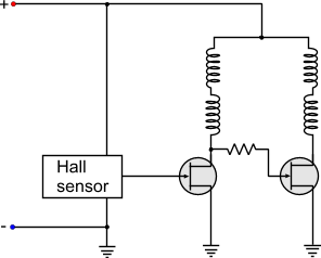
The connector of a 2-wire fan has a red and a black cable. The red cable goes to the positive of the power supply and the black to the negative. Usually, for more flexibility, they have a male-female 4-wire molex power connector. In one end of the connector the fan is connected in parallel with the 12V (YELLOW - BLACK). Therefore, the fan is powered normally and the cable of the PSU can be used to power another device.
3-wire PC Fans
A 3-wire PC fan  Yet another 3-wire PC fan with different wire colors Yet another 3-wire PC fan with different wire colorsA very common type of PC fan. These fans introduced the "tacho" for the first time. The first two wires are the power supply of the fan. The third wire, comes directly from the output of the Hall sensor. This output generates 2 pulses per one revolution of a fan. The fan is then connected to the motherboard. From the third wire, the motherboard can "read" the tacho of the fan and see if the fan is running and with how many RPMs! It is a great innovation! If the motherboard sees no pulses or very low rpm, then the characteristic buzzer sounds to inform the operator that something is not ok. The internal diagram of a typical three-wire fan is as follows:
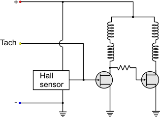
It seems that for once more, the manufacturers did not have the same wire provider, or their wire providers did not have the same colored-plastic provider... Two fans with 3-wire connectors may not have the same wire colors. Thus, instead of using the colors to distinguish the function, better go with the connector that is standard. No matter what color the cable has, it will be plugged in the same motherboard connector! So,as you look from the key-side of the connector, number 1 is the most left pin :
- 1: Negative power supply
- 2: Positive power supply
- 3: Tacho
 |
 |
BLACK: Negative
RED: Positive
YELLOW: Tacho |
BLACK: Negative
YELLOW: Positive
GREEN: Tacho |
4-wire PC Fan
This is the most modern type of PC fan. This fan is designed to be controlled with a PWM signal and increase or decrease its RPM. All fans actually can be controlled with PWM, but this particular type can also provide tacho feedback simultaneously, something that the 3-wire fan cannot do -under normal circumstances. The 3-wire fan powers the Hall sensor and the controller from the same line that the coils are powered. Thus, if someone tries to send PWM pulses to the coils of a 3-wire fan, the same pulses will arrive at the controller. The controller will then malfunction, because it needs constant current to operate. As a result, the third wire will not provide correct readings.
Unlike the 3-wire fans, the 4-wire fans have a slight change that eliminates this problem. The controller and the Hall sensor are always powered with constant current. A transistor (fet) is placed before the coils. The base of the transistor is actually the fourth wire. So, the PWM pulses are driving the transistor. The coils receive these pulses through the transistor, but the controller along with the Hall sensor are not affected at all. This change can be seen in the internal diagram of a typical 4-wire fan:
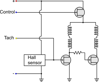
Usually, the diagram is more complicated than this. This is to give you an idea about the principle of operation of the PC PWM Fans (as used to be called). The controller actually checks the PWM input pulses and sends pulses to the transistor accordingly. If the PWM Duty cycle is bellow a threshold value, then the fan either shuts down, or it remains in a stable 'LOW" rpm. There are also fans that even with 0% duty cycle, they keep on running at this 'LOW' speed. This is usually done in critical applications that even if the external controller fails to operate, the internal fan controller will bypass the signal and will keep the fan running.
As for the pinout... Just do not trust the colors. As you look from the key-side of the connector, number 1 is the most left:
- 1: Negative power supply
- 2: Positive power supply
- 3: Tacho
- 4: PWM control
 |
 |
BLACK: Negative
YELLOW: Positive
GREEN: Tacho
BLUE: PWM Control |
BLACK: Negative
RED: Positive
YELLOW: Tacho
BLUE: PWM Control |
Can I connect a 3-wire fan to a 4-wire connector?
Yes you can. If you notice the pinout of the fans, the 3 first pins are the same for the 3 and 4 wire fans. Also, the keys are the same for both connectors. The 4-wire connector has smaller back-key to accept the smaller 3-wire fan connector keys. The fan will always run at full speed (as the control pin will not be used), but the rpm feedback (tacho) of the fan will operate normally and the motherboard will read the rpm normally.
Can I connect a 4-wire fan to a 3-wire connector?
 A 4-wire fan connected to a 3-wire connector. No problem! A 4-wire fan connected to a 3-wire connector. No problem!Yes (and no) and Yes. Although the connector is larger, the keys of the 4-wire fan have the same distance as the 3-wire connector. The fan will operate at full speed all the time, as the 4th wire from the PWM control will be on air. The motherboard will normally read the rpm feedback from the fan tacho.
Now, i am not quite sure about the internal connectivity of the 4-wire fans. No matter how may fans i tested, and no matter how many sites i visited, i found no clue that this configuration will fail. This means that the PWM control line must have an internal pull-up resistor, so that when the pin is unconnected, the control FET will be kept always ON. There could be a manufacturer though that maybe felt like making something different, and either he removed this resistor or replaced the FET with different channel than normal. I do not know why anyone would do this! But i have not find anywhere a norm that declares if the fan MUST operate or not with the 4th wire unconnected. A site-reader sent me a link from Intel (click) which definitely shows that a 4-wire fan can be connected to a 3-pin connector, so i suppose that this is the norm i was looking for. Thanks a lot Mysteron347.
Anyway, what you only have to do is to test it. Either plug it in and see what happens, or give power yourself to the first 2 pins (negative and positive). If it rotates, then no problem!
Comments
At 30 March 2016, 10:02:26 user Adam wrote: [reply @ Adam]@Giorgos Lazaridis Hi and thank you for the very informative read! I've just read through all the comments to check that this hasn't been asked... Long story short: Can I fit a resistor to either the 12v or PWM wire on a 4-pin CPU fan to retain the automatic PWM control, yet reduce the maximum speed? The fan is 12v 0.75A and spins at 6000rpm at 100% which makes quite a bit of noise. If so, which wire should I fit the resistor to. Whether reducing the 12v would effect power to the inbuilt fan controller. Or whether the resistor would even make a difference to the PWM considering its the pulse width that matters and (possibly) not the voltage of the pulse?
More info if required - The computer is an Alienware x51 and the cpu fan is a slim 80x80x20mm fan (almost all are 25mm high - which doesn't suit the Small form factor case and its plastic deflector to push air out the back of the case). I have searched long and hard and found a .45A fan which would cost $20 and take about a month to arrive, or I could fit a $0.50 resistor of 12 ohm 5w and reduce the max speed that way. Plus you get a sense of achievement, heh.
Cheers from Australia!
At 28 March 2016, 5:39:41 user Sherif Omran wrote: [reply @ Sherif Omran]does the 2/3/4 fan operate as a dynamo if we rotate the fins per hand? or is there a diode that stops current output?
thanks
At 21 March 2016, 16:04:05 user Lyle Stotz wrote: [reply @ Lyle Stotz]I simply used too much thermal compound and my cpu fan ran at full speed. After removing some of the compound all is well.
At 13 March 2016, 17:04:41 user Bryan wrote: [reply @ Bryan]I have a Delta AFB 048EH cooling fan with four wires. The colors, however, are not the normal ones. This fan has red, blue, white and yellow! Want to use just the and - and run the fan all the time. I don't know which wires are and -. Usually it is red and black or on some fans yellow and black. Neither of these combinations exist on my fan. Can anyone help. Thanks.
At 14 February 2016, 17:40:26 user Luiz Fernando wrote: [reply @ Luiz Fernando]Very usefull page helped me a lot. Thanks for write this instructive article .
At 21 January 2016, 17:50:23 user Johan wrote: [reply @ Johan]Hi! If I cut the cables from 4-wired fan and just connect it to a power source, will it run at full speed then? If not, can I make it run at full speed in some way? I'm not using it in a computer.
Regards, Johan
At 22 December 2015, 5:25:09 user khaled ahmed wrote: [reply @ khaled ahmed]
At 3 December 2015, 15:06:00 user Niels Vrijland wrote: [reply @ Niels Vrijland]Dearest,
I use stand-alone 3-wired fans for ventilation of a room. How could I connect the third wire to control the speed of the fan?
Kind regards, Niels
At 20 November 2015, 10:50:02 user Max wrote: [reply @ Max]this helped me a lot. thanks for writing stuff like this.
At 29 October 2015, 23:10:59 user Chris wrote: [reply @ Chris]I cannot find the exact same 24V 1.4W two pin fan. I found a 24V 1.7W fan that is three wire and I figured it was close enough. can I simply tape off the tacho wire and will the 0.3 Wattage difference likely be a big problem? this is for a Viking refrigerator.
basically I'm looking for any comparable fan to replace the existing Sunon KDE2406PTB3 DC24V 1.4W fan.
At 25 October 2015, 6:57:55 user Giorgos Lazaridis wrote: [reply @ Giorgos Lazaridis]
At 24 October 2015, 10:25:59 user Louis wrote: [reply @ Louis]Will I damage the fan if it connect 12v to the wrong pin? 3pin version.
At 4 September 2015, 16:04:49 user jaco wrote: [reply @ jaco]Hi I have a 4 wire cpu fan and I find that if I power it up and put a second supply pos to green and com yo blue but using a resistor. It spins at max speed
At 19 August 2015, 21:23:56 user Giorgos Lazaridis wrote: [reply @ Giorgos Lazaridis]@john copertino Yes you can, no problem
At 13 August 2015, 13:24:41 user john copertino wrote: [reply @ john copertino]Can I connect a 3 wires fan just using the positive and negative and leave the Tach wire unconnected. Would this be harmful to the fan.
At 8 August 2015, 15:52:37 user Viggo wrote: [reply @ Viggo]Thanks for this instructive article. It helped me :)
It is argued, that the 3 wire interface makes it impossible to have both PWM-control and usable taco signal. I think it should be possible with some workarounds. The fan manufacturers can include a diode and capacitor in order to maintain supply voltage to the hall element controller. Another possibility is by PC software. When you know the actual supply state (on and off) you can interpret the taco signal and it should be possible to find the right RPM value - just a little more complex software.
But now the 4-wire interface has been introduced with the confusions to many people having now two kinds of interfaces.
I did also find Intels 4-wire interface spec. from 2004:
http://www.formfactors.org/developer%5Cspecs%5Crev1_2_public.pdf
I noticed a motherboard from ASUS having three 4-pin interfaces to fans. Only one (for CPU cooler) made use of the interface. The two others had 5V constant to the PWM signal. I seemed like it was possible to make PWM control on the power supply pin as done on previous ASUS motherboards.
At 7 August 2015, 10:38:31 user Viggo wrote: [reply @ Viggo]Thank you very much for this article. It made me understand this issue.
I do actually wonder about why the extra pin 4 has been introduced, because there should be possible workarounds. Making a new kind of interface will always create problems for many people.
Workarounds for the fan manufactures can be a small circuit including a diode and capacitor able to keep supply voltage on the hall element controller. In this way you can have a stable taco signal independent of the PWM control. Another work around is by software in PC. If you measure the taco signal at the same time you know/control the output PWM-power signal (high or low), then this information should provide you the real taco signal information you want. With some proper software it should be possible.
So perhaps some makers of fans or PC software for fan control already did this - I don't know.
However someone in this business did decide to go make a new 4-pin standard.
At 3 August 2015, 1:38:33 user abc wrote: [reply @ abc]for the 3-wire fan, wire colours: you say the centre pin is always positive. well it's not on my sony vaio laptop. im glad i didnt do any damage following your instructions mate.
At 2 May 2015, 2:39:17 user Steve Horvath wrote: [reply @ Steve Horvath]Hello!
Yesterday (04/30/2015) I bought a Hyper 212 EVO CPU Fan because the old Fan installed almost 3 years ago was nearing its lifetime with a few weeks to spare. Due to the fact the summer is approaching and the ambient temperature will get higher, I wanted to be sure that my CPU was being cooled off!! As additional cooling, I also installed two 3x3 Inch Fans onto the Chassis directly above the Hyper 212 EVO CPU fan to move the heat outside of the Chassis. The installation was very simple as both of these Fans had a Molex connector, and they both work perfectly since their install with my AGS Series SATA ATX 450 Watt Power supply. I must say that I was fortunate to have small holes on my Chassis that made it easy to screw the fans into place and secure them.
For those whose Chassis don't have any holes, the solution is to drill a hole or two where you could install small Fans to remove excess heat from your device and keep the CPU and it's environment cool for optimal performance.
Best Regards, Steve, Chicago, IL
At 1 May 2015, 10:18:13 user Giorgos Lazaridis wrote: [reply @ Giorgos Lazaridis]@Patrick Sure, you can simply make a PWM fan controller or linear voltage controller. check out my circuit pages.
At 1 May 2015, 10:13:07 user Giorgos Lazaridis wrote: [reply @ Giorgos Lazaridis]@Stephen get a 5V fan, stick it under the laptop power through usb. Or get a 12V fan, make a boost circuit 5 to 12V ...
At 1 May 2015, 10:11:47 user Giorgos Lazaridis wrote: [reply @ Giorgos Lazaridis]http://www.pcbheaven.com/forum/index.php?topic=1860.0
At 29 April 2015, 7:29:49 user Fan wrote: [reply @ Fan]I adapted it for my need
http://www.pcbheaven.com/forum/index.php?topic=1860.msg7453#msg7453
At 27 April 2015, 7:46:07 user Stephen wrote: [reply @ Stephen]Hi,
Just a quick question, could a person build up an external like fan for a laptop if so how would you go by doing that.
thanks
At 24 April 2015, 7:43:38 user Fabrice wrote: [reply @ Fabrice]Hi, nice page, I think I'll find my heaven here!
A musician friend of me with no money just got an old PC Core 2 Duo with two 3 pin fan headers and a very noisy ~3300 RPM 4 pin CPU fan, so you guess it runs at full speed. After I read this page and understood some more about the difference between 3/4 pin fans I hope I could tweak for him some little pcb to drive his CPU fan speed depending on the heatsink temperature.
Is there and already roughly calculated schema that would do the job?
I found this that could be the input : http://english.cxem.net/home/home24.php
and this for the 4 pin output: http://www.pcbheaven.com/circuitpages/High_Frequency_PWM_Fan_Controller/ (4 wires one, and if I read Giorgos correctly, R1 is already in the fan)
But I don't know how to interface. I'd rather not use PICS or Arduino as I'm poorly skilled.
Thank you
At 9 March 2015, 23:16:50 user Patrick wrote: [reply @ Patrick]Okay, I have a question for you guys... I have a four-wire (red black yellow blue) 12v fan out of an old computer that I've converted into a USB-powered desk fan. I cut off the end of an old USB cable and connected the black wire to black and red wire to red. Simple. So now my question is, would it be possible to use the blue wire to create some way to adjust the fan speed, like with a knob or something. Or would I be better off just buying a knob that can adjust the power and connecting splicing it into the red wire?
At 28 February 2015, 13:49:52 user Paulal John wrote: [reply @ Paulal John]Very helpful. Thanks alot for it
At 15 October 2014, 0:50:11 user mastero wrote: [reply @ mastero]3 types of Fan wires:
1 - fan with 2 wires - Black - Red
2 - fan with 3 wires - Black - Red - Yellow
3 - fan with 4 wires - Black - Red - Yellow - Blue
(warning never ever mix Yellow & Blue with Red fan will die -no repair)
Black = Ground (negative)
Red = wire is positive 12V, 7V, 5V
Fan only need two wires Black & Red to work.(at full speed)
Yellow = sends fan speed to motherboard.
Blue = montherboard controls fan speed.( disconnecting blue wire fan will start run on full speed)
if your motherboard has 4 pins fan connector -you can use 2, 3, 4 wires fans.
if your motherboard has 3 pins fan connector -you can use 2, 3, 4 wires fans (4th wire will be ignored).
if your motherboard has 2 pins fan connector -you can use 2, 3, 4 wires fans ( 3rd & 4th will be ignored).
Most fans wiring from left to right ( 1 = black, 2 - red, 3 - yellow, 4 - blue ) if colors of wires different ( you have to find most important 2 wires black & Red (Ground & Positive)
At 19 September 2014, 15:58:21 user Karen wrote: [reply @ Karen]Does this also apply to the fans for a tv?? my lamp cooling fan is the same as pc fan but wires are blue, black and gray and fan I bought is blue, black and red???
At 5 September 2014, 18:10:16 user CK Ooi wrote: [reply @ CK Ooi]@Jarom @Jarom @Jarom @Jarom @Jarom @Jarom @Jarom @Jarom @Jarom @Jarom @Rene @Rene @Rene @Rene @Carl @Carl @Carl
Thanks for the useful information. Can I connect 3-wire PC Case fan just to positive and negative 12V power supply and ignore the Tacho wire. Is there any side effect to the performance of the fan ?
Thank you very much for your help.
At 4 September 2014, 3:24:26 user Dana wrote: [reply @ Dana]Can someone PLEASE advise? Removed broken fan from my Dell Inspiron and it says Sunon Maglev KDE1209PTVX DC12 - 7.0 w and in tiny print it says 13.ms.B3035.AF.GN -- do you know what this represents? I found a fan online that said it was a Magelv DC12 but had different tiny lettering: 13.ms.B2590.AF.GN -- Question: are these compatible fans and what is the difference between them? Thank you very much for any help!
At 2 September 2014, 17:16:17 user Peter wrote: [reply @ Peter]Thanks for the clear photos and its brilliant! helped with a cooler master illuminated 12v 3 pin uncoded wire fan, and you pics gave the location and it works....! Thank you
At 2 August 2014, 20:46:24 user Matt P wrote: [reply @ Matt P]Very informative, thanks! I am wanting to use a PC fan to measure wind speed. Any suggestions on how to do this, hall sensor would seem to do the trick. What about measuring any current created from the fan running backwards, would it even do that? I am looking measure on a relative basis, not actual wind speeds.
Thanks for any guidance.
At 24 July 2014, 13:42:33 user Ash wrote: [reply @ Ash]Hey man,
I have a 3 pin fan and it use to run at low speed when idle but now it runs at high speed all the time, it's an old fan so I was wondering if the tachometer is broken?
Thank you very much :)
At 8 May 2014, 21:22:11 user Michael Flynn wrote: [reply @ Michael Flynn]Hi Giorgos,
I just want to thank you for this great resource and for answering every new comment within hours. That is terrific and a great service to the creative comunity!
To all who are interested in turbine fan BLCD computer fans as generators:
I've found that SunOn-bran fans that have "Maglev" levitating bearings are uniquely suitable for generating electricity as generators as they spin.!!!!!! (Maglev is their trademarked name but it is unique because it involves hovering touch-free bearing s that are useful as a magnetic field for generatinging electricity) To all experimenters: Try spinning SunOn MagLev fans, of the highest possible voltage, as wind generators.
Michael Flynn
wwww.FunExhibits.com
At 8 May 2014, 6:12:52 user Scoute wrote: [reply @ Scoute]@Giorgos Lazaridis, thanks for the reply. I was also thinking on same lines. Will keep PCH users posted if I hit any luck with it. Thanks for comment.
At 7 May 2014, 7:26:31 user Giorgos Lazaridis wrote: [reply @ Giorgos Lazaridis]@Scoute Well actually yes, if you put the multimeter on some fans (not all) and rotate the blades you will see some voltage building up, but the power is ridiculously low.
At 7 May 2014, 3:56:22 user jrohm wrote: [reply @ jrohm]I wanted to add my 2cents to the 3-wire fan diagram. My experience has been that a number of vendors use highspeed 3-wire fans that look like normal 80mm units but have reversed polarity and are designed to run around 3000RPM instead of the normal 2000-2200RPM. They work the same way but the pinouts are differet, presumably to keep people from accidentially interchanging them.
At 2 May 2014, 7:58:43 user brazendan wrote: [reply @ brazendan]Giorgos -- Thank you very much for posting this. very informative. I was hoping someone would find a reliable way of disassembling these things so that we can clean up the bearings! Oh well!
Hey, one thing I ran across is that some three wire fans have a "rotor locked alarm" instead of a tach. I can't figure how to distinguish one type from the other by just looking at them. If anyone has ideas on this I'd love to hear them! I have a old printer with a 3-wire fan and need to figure this out before buying a replacement fan.
At 26 April 2014, 11:24:58 user Scoute wrote: [reply @ Scoute]I was watching a video on YouTube, someone was using PC Fan to light up a bulb. We know he had hidden 6v batteries in the fan, but question is that if we able to rotate PC Fan at high speed clock wise/ant clock wise, will the FAN can generate power even to if it can power a LED?
At 18 April 2014, 17:35:40 user virtual panda wrote: [reply @ virtual panda]Thanks this was really helpful. I ran out of fan ports on my mother board and i was thinking of combining the cables but i wasn't sure what the third pin was used for.
At 20 March 2014, 15:12:22 user Vietredneck wrote: [reply @ Vietredneck]@Rene I don't know how it works for the 4-pin connectors, but with my 3-pin Delta fan, all I did to adjust the voltage down was rearrange the pins to the molex adapter to lower the voltage to 7V since my fan was too loud. You MIGHT be able to do that with your 4-pin by connecting straight into the PSU via molex. Just a disclaimer, I'm no pro.
At 7 March 2014, 1:18:17 user sparky wrote: [reply @ sparky]Thanks for the info. I lack this type of info in my brain, hpefully I will now gain some insight.
At 2 March 2014, 20:32:37 user Carl wrote: [reply @ Carl]I've tried numerous times to put 12V. to a fan with 3 and 4 pin connectors.
The only way I was able to get a fan to run was to put a AC or Pulse from a signal generator on the toucho connection. The best bet is to find fans with just TWO wires. Then they should work unless the fan is shot. Also, polarity is a key, if you have reverced the polarity, the fan will not run. Apparently there is a DIODE in series with the motor.
At 2 March 2014, 17:04:06 user Rene wrote: [reply @ Rene]How do i get a 4 pin fan to run on 12v dc? Doing a project with a peltier and need some cooling.....
At 16 February 2014, 3:40:48 user TravisAZ wrote: [reply @ TravisAZ]Giorgos, you are the man. 4 years later this explanation and illustration are both helpful and dead on, and best of all -- entertaining. Ignore the fan manufacturer's wire vendor color selection and focus on the pin-out.
At 30 January 2014, 22:33:34 user Bob JimBob wrote: [reply @ Bob JimBob]Thanks for the image, it took me a while to fully understand how to read the connectors on the fans, but I was able to figure out how to take a proprietary Dell connector for a 4-pin fan and rig a 3-pin fan to it.
At 2 January 2014, 20:05:22 user Giorgos Lazaridis wrote: [reply @ Giorgos Lazaridis]@noufal In the circuits session you will find some schematics:
http://www.pcbheaven.com/circuitpages/
At 2 January 2014, 20:03:15 user Giorgos Lazaridis wrote: [reply @ Giorgos Lazaridis]@Jarom Definitely. Simply power with 12V the red and the green
At 2 January 2014, 13:14:18 user noufal wrote: [reply @ noufal]Thank you. Great job. but could you please provide the link for a complete circuit diagram of a practical 4-wire fan?
At 2 January 2014, 3:21:44 user Jarom wrote: [reply @ Jarom]I have just purchased 2 fans with 3-pin connectors. My case has a number of 2 pin outputs for multiple case fans, however the fans do not seem to be working. all connections seem good. Is it possible for a 2-pin outlet to power a 3-pin fan?
At 30 December 2013, 23:45:33 user Giorgos Lazaridis wrote: [reply @ Giorgos Lazaridis]@jemas you will have to do major hack job since the circuit is embeded in the fan
At 30 December 2013, 12:36:31 user jemas wrote: [reply @ jemas]@Giorgos Lazaridis
is it possible to bypass the circuit? by leaving the tachometer part powered and disconnect the dc motor?
At 30 December 2013, 8:36:10 user Giorgos Lazaridis wrote: [reply @ Giorgos Lazaridis]@jemas Actually there isn't. Check the drawings in this page - You will see that without power the hall sensor and the rest of the circuit are not working.
At 26 December 2013, 14:23:31 user jemas wrote: [reply @ jemas]Thank you for your reply. I have a 3 wire fan 1 ground, 1 power and 1 tachometer signal. When i put a voltage of 5V on the voltage line and i read out the tachometer, i get perfect readings ( I am using labview to measure this). But when i disconnect the 5V, i do not get readings from the tachometer. Is there anyway you might suggest to bypass this? So that i don't let the fan work with voltage, but purely by spinning it by hand and still read out the tachometer? That would be very helpfull.
At 26 December 2013, 10:45:14 user Giorgos Lazaridis wrote: [reply @ Giorgos Lazaridis]@JeMas The output of the fan is not a 5 signal, its a pull down signal, which means that when you remove the pull up signal (in your case the 5V) the signal seems to go away.
At 23 December 2013, 16:20:08 user JeMas wrote: [reply @ JeMas]Is it possible to use the tachometer without making the fan turning? I would like to use the tachometer to measure frequency of a shaft. I can perfectly read out the frequency while the fan is powered and running, but when i disconnect the 5V, the signal disappears. Do you might have an idea what this may cause and a solution for it?
At 6 December 2013, 6:47:14 user Giorgos Lazaridis wrote: [reply @ Giorgos Lazaridis]
At 30 November 2013, 11:49:03 user needless wrote: [reply @ needless]I have a 2 pin fan can i connect to a 4 pin connector?
At 26 October 2013, 5:01:46 user tom k. wrote: [reply @ tom k.]An excellent description. Very well written. Thanks for your good work.
At 17 October 2013, 8:45:56 user seergio wrote: [reply @ seergio]good information ,very useful
At 12 October 2013, 9:04:45 user Giorgos Lazaridis wrote: [reply @ Giorgos Lazaridis]@Carl The way you put it makes me believe that you've mistaken the tacho with a power wire... Check it again.
There is no O, only zeros.
At 6 October 2013, 21:43:50 user Carl wrote: [reply @ Carl]I have several 3 wire fans out of PCs, Voltage to the and - doesn't run the fan without a pulsing or AC voltage to the Toucho connection. I put AC or pulsing square wave to the Toucho, it works, as soon as Toucho is disconnected , the fan STOPS!
I accidently clicked the Unsuscribe link. OOOPS, I'm Bac,
Also on your Captcha, It would be nice to know if it's a 0 or O. OK, let's see if it works!
0 or O, second Try! At least I don't have to guess it again. :-)
At 6 October 2013, 7:14:13 user Giorgos Lazaridis wrote: [reply @ Giorgos Lazaridis]@paul Yes just remove the tacho wire
At 5 October 2013, 18:10:21 user paul wrote: [reply @ paul]I would like to use a 3 pin fan continously without tacho.
Can I just disconnect the tacho wire?
I measured 4 Volt between tacho and negative and 0 Volt between positive and negative for a 12 Volt fan. The fan was not running. Is this normal?
At 13 September 2013, 21:33:25 user Giorgos Lazaridis wrote: [reply @ Giorgos Lazaridis]@lindsay norris Sure you can. It will work
At 13 September 2013, 16:38:55 user lindsay norris wrote: [reply @ lindsay norris]can I just hook up the positive & negative wires only in a 3 wire system. I do not require speed control.
At 31 August 2013, 10:23:51 user Pashka wrote: [reply @ Pashka]Thank you guys! You prolog my life a little:
https://www.facebook.com/ComradePashka/posts/508813599194853
:)
At 30 August 2013, 16:30:22 user Giorgos Lazaridis wrote: [reply @ Giorgos Lazaridis]@jinky Most likely no, because PC fans have built in controllers. Hack one and remove the controller board, then connect wires to the coils and you have a generator. The efficiency will be bad though...
At 30 August 2013, 16:21:10 user Giorgos Lazaridis wrote: [reply @ Giorgos Lazaridis]@leo Normal PC fans don't have automatic system to change their speed. They get PWM pulses from the mobo and they return their speed
At 14 August 2013, 12:30:07 user Carl wrote: [reply @ Carl]I did try this. YES it worked.
As for a previous comment of WHY, I have a bunch of these 3 whire fans so I was looking for a way to use them to cool a Laptop. TRUE, using a square wave generator is over kill, but the laptop in question isn't going to be going any where because of it's over heating problem. So I was looking for a way to use it as a stationary PC in my recording studio. Besides, I'm wanting to use what's available to me at the time.
At 13 August 2013, 22:46:14 user Giorgos Lazaridis wrote: [reply @ Giorgos Lazaridis]@Carl R. Sure a square wave generator would work but... why use one?
At 10 August 2013, 4:53:51 user jinky wrote: [reply @ jinky]is it possible to generate a voltage if I supply wind in the cooler and the blades rotate? how much is the possible voltage produced?
At 3 August 2013, 17:11:30 user leo wrote: [reply @ leo]@Giorgos Lazaridis
I really dont think so. dont this sort of fan have a system to speed down unless the motherboard gives another instruction?
I really dont know about this...
At 2 August 2013, 16:18:53 user Carl R. wrote: [reply @ Carl R.]Thanks for commenting about the Capcha, From what I've Experienced, the GOOGLE Captcha is basically a JOKE! I'm used to hearing synthesized voices with my Screen reader on my PC, but every time the GOOGLE voice tells you what the number or letter sequence is, It's usually very difficult to understand. As for why you use the captcha, I completely understand. Thos spammers are a pain in the ___!
As for TWO wire fans starting up fast then slowing down, I'm CLUELESS! I suspect the fan is ready for the garbage can. A simple DC moter shouldn't be that complex.
Also, looking at the comment thread, sounds like others are trying to cool their laptops. As for what I've heard, it's very common. I think I'll just scrap out some old power supply's for fans that run on 110 V AC.
For running a DC motor that has 3 wires, I was thinking of useing a SQuare Wave Generator to supply the pulse. Would that work?
As for reading your captcha, I magnify my screen reader to 6x or 8x in order to see the lettering on the captcha., sometimes, I need to go larger on some captchas., so far, yours isn't the worst i've seen.
At 2 August 2013, 10:39:19 user Giorgos Lazaridis wrote: [reply @ Giorgos Lazaridis]@Carl R. I had a huge spam attack 6 months ago, the provider kicked me away from his servers and i had to move the complete site to another provider. I used to delete tons of irrelevant messages when i had no captcha. Spamming the comments also sends hundreds of emails draining out my daily limit. I had to break the site into 2 different servers to save it from the spammers. So the use of captcha is not an overkill. I should have used google captcha with text to speech. Now that you mention this, i will put it on my future plans.
At 2 August 2013, 5:24:22 user Giorgos Lazaridis wrote: [reply @ Giorgos Lazaridis]@leo Maybe the fan has a problem?
At 30 July 2013, 22:48:33 user Carl R. wrote: [reply @ Carl R.]Thanks for the information. I was playing with some old 3 wire fans trying to rig a way to externaly cool a laptop. I don't want to spend the $$$ for a docking platform. I have a few 3 wire that I could not run but I rigged a 2 wire to pull air through it. I was looking at small fans to push air through the bottom of the laptop but they are 3 wire.
It seems these fans mostly ALL are 3 wire coming out of old Pentium machins. As for the plug, I just cut it off and wire it to an Ac to DC adapter from 9 to 12 volts. I guess i'll just look for more 2 wire fans to use.
EXTRA NOTE: The use of the CAPCHA on this site is a bit OVER KILL. These things are a pain for those of us who are Visually Impaired. Being Legally Blind, I use text to speach to tell me what's on the screen, these CAPCHAs are very difficult if not impossible for us BLINKS.
At 30 July 2013, 20:22:46 user virgil wrote: [reply @ virgil]These are not "3-phase" motors. Those are for large industrial uses that require three phase (Y or Delta configuration) to operate. It's like your electric dryer (which uses 220V 2-phase), only bigger.
These small motors have 3-pole or 4-pole stator windings. It is how many sets of coils you see on the inside.
The capacitors are there to make the motor self-starting. The fan may have previously stopped in a position that the fan will not spin when the coils are energized again. The capacitors charge up on startup to give the fan a little "kick".
At 22 July 2013, 13:17:49 user leo wrote: [reply @ leo]hi there!
I found a fan that I would like to use for cooling my laptop.
fan is 12v / 0.68A
I am using a dc adapter to feed it.
adapter is 11-13.5v / 1.18-0.96A
when I connect them, the fan starts running pretty quick, but inmediately after it slows down its speed, what makes me think that the fun is ready to run very fast, but something is making it slow down.
how can I force it to run at full speed?
thanks a lot!
At 18 July 2013, 1:49:27 user Michael Flynn wrote: [reply @ Michael Flynn]I found two capacitors inside my BLDC fan. Can anyone explain why they are there, what they are for and how they connect in the circuit?
At 4 May 2013, 7:46:27 user Giorgos Lazaridis wrote: [reply @ Giorgos Lazaridis]@John Usually 2. 3 phases can also be small - HDDs have 3-phase bldc
At 2 May 2013, 15:38:31 user John wrote: [reply @ John]Hi, for typical computer fans, how many phase does the brushless dc motor have? Initially, I thought 3 phase (standard) but then was reading other
websites and said 3 phase brushless dc motors are big.
Thanks.
At 21 April 2013, 11:36:16 user Giorgos Lazaridis wrote: [reply @ Giorgos Lazaridis]@George Fischer 50% PWM duty cycle means 50% power delivered to the fans. The speed depends on the construction of the fan. Ideally, this would be 50% speed(though this is far from true)
At 17 April 2013, 3:50:40 user Tom wrote: [reply @ Tom]Hi,
For the computer fans, what are some of its component values like it's Resistor, Inductance, how many poles? what values would a standard speed control computer fan have? Thanks.
At 15 April 2013, 15:01:44 user George Fischer wrote: [reply @ George Fischer]Hi,
my knowledge of electrical problems is quite limited but I would like to hook up a couple of case fans to a PWM controlled CPU fan. I suppose if CPU fan is say 1500 rpm max. and the case fans as well, then they would all run at the same speed. But what happens if you mix fans with different specs?
For example if I used case fans of 1200 rpm max. (or any other max. speed lower than the CPU fan), would they run at 1500 rpm and presumably get overloaded or would they just run at their max. of 1200 rpm? Accordingly if the CPU fan runs at 50% of its max. speed would the case fans run at 50% of their max. speed?
Thanks in advance
George
At 15 March 2013, 15:04:19 user Giorgos Lazaridis wrote: [reply @ Giorgos Lazaridis]@Lily you could have a voltage to frequency setup - the higher the voltage, the faster the frequency. THis can simulate the speed of rotation of the fan
At 12 March 2013, 21:07:45 user Lily wrote: [reply @ Lily]Hi,
I have a school project about computer fans. I am suppose to design a computer fan motor that controls the speed based on the temperature. I am using PSIM to simulate it. I chose a Brushless DC motor and as a replacement for the temperature values, I just used a step function as the input. My initial circuit is: Battery>step function (Temp)>(desired speed based on temp)>comparator> thyristor bridge>BLDC>Speed Sensor with feedback to comparator.
So I was wondering how would you start this using power electronics to simulate a computer fan or what advice would you have?
Thanks!
At 5 March 2013, 20:08:35 user Giorgos Lazaridis wrote: [reply @ Giorgos Lazaridis]@GaryC If you inject PWM to a 3-wires fan, you will get PWM at its feedback as well making it impossible to measure. I've tried some methods to solve this problem, the best was this one:
http://www.pcbheaven.com/circuitpages/PWM_3_Wires_Fan_Controller_with_RPM_feedback
At 3 March 2013, 2:23:22 user GaryC wrote: [reply @ GaryC]Hi, nice article,
I want to use 3 wire fans (not connected to a Mobo) in PWM but although you state all fans can work that way, you then state that the controller (in the fan) gets screwed up. Will it work or not? I wanted to use the speed feedback too, but your article saws no. That alerts me to possible work to see if I can make it workaround. I plan to use PIC or PICAXE as controller with necessary buffering/interfacing.
Thanks Gary
At 13 February 2013, 22:31:14 user J.P. wrote: [reply @ J.P.]There is another 4 wire type not mentioned here. They're call 'speed stable' or 'speed regulated' in contrast to 'free running'. A PWM signal is fed into the motor controller to set the speed and the motor controller will do the best it can to make the fan run at the set speed until it reaches it maximum rated power. As a colleague of mine put it: these fans do not stop for a pencil or a childs finger.
This in contrast where the external PWM signal is directly used to control the motor. A speed stable fan does not require a PWM frequency above 20kHz to avoid whistling as the actual motor controller does the hard work.
With speed stable fans, the tacho output can be changed into a trip point alarm. Nidec by default activates this wire when the actual speed is 70% or worse from the set speed.
http://www.nidecamerica.com/fanpdfs/c2008_0203.pdf
At 10 February 2013, 14:52:55 user Giorgos Lazaridis wrote: [reply @ Giorgos Lazaridis]@Radovan Horak Actually, i really cannot tell. I can only suspect that no one would have embedded such a "security" functionality for the mad man that wants to bypass the feedback. I strongly believe that the 555 phantom fan will work.
At 8 February 2013, 8:00:27 user Radovan Horak wrote: [reply @ Radovan Horak]Hi Giorgos,
thanks for this wonderful website!
I come back to the post written by Dan Canham 3 April 2012 regards a fantom PWM fan tach output.
For about a week I have new HP Z420 Workstation. This otherwise beatiful computer is fitted with the PWM fans which are whatever but not quiet. Of course, when you plug-off them the BIOS starts protest. Furthermore when you disconnect the PWM fan built in PSU the computer stops working at all.
To solve the noisy problem I desided to tune it up by liquid cooling. But I will need to replace physical fans by let say "fantom" ones. I have the same idea - to drive motherboard sensor pin by fantom tach signal generated by 555 based circuit... But not sure whether there is some BIOS feedback check between PWM sent to the fan and tach signal returned. If yes the most complicated circuit which is able to mimics all behavior aspects of a PWM has to be developed.
What is your point of view?
Radovan
At 23 November 2012, 15:17:29 user Giorgos Lazaridis wrote: [reply @ Giorgos Lazaridis]
At 22 November 2012, 18:43:20 user waqar javaid wrote: [reply @ waqar javaid]is it possible to use motor of 4 pin fan as a servo motor
At 22 June 2012, 14:38:22 user John A. Johnson wrote: [reply @ John A. Johnson]A most useful page! Thank you!
Now I have information that may help me deal with a problem that has arisen with my old (circa 2003) Samsung HLN5065wx DLP HDTV. A couple of weeks ago an error message suddenly appeared on the screen indicating a problem with "Fan 2." After much searching, I found a page (http://www.fixyourdlp.com/forum/viewtopic.php?f=10&t=596&p=2047#p2047) indicating that a failing fan could be replaced by an ordinary 3-wire PC fan. Good to hear since an official replacement fan is $23 S&H and I have old PC fans lying around. I haven't actually made the replacement yet because I revived the TV fan with blast of compressed air, but if it does fail I will be able to match the wires correctly (they are different colors).
At 6 May 2012, 23:48:20 user Mitch wrote: [reply @ Mitch]Thanks, for taking the time to post. The information was very good in helping me choose a power supply replacement fan.
At 18 April 2012, 1:06:54 user Ogawa wrote: [reply @ Ogawa]On the web found this interesting cable, this could mean that yes, it's possible :-)
http://www.ainex.jp/img/large/wa-864ps_s.jpg
At 17 April 2012, 11:08:40 user Giorgos Lazaridis wrote: [reply @ Giorgos Lazaridis]@Ogawa normally yes, this should be possible. I have never test it though
At 17 April 2012, 10:40:55 user Ogawa wrote: [reply @ Ogawa]I have a question, just got a motherboard with 3 case fan connectors, two are 4 pins and one is 3 pins.
I want to buy 3 fans with 4 connectors, only that there's going to be one fan that I wouldn't be able to control...
Thinking on connecting just the PWM control cable of the 3rd fan to the 2nd fan, controlling those fans with one controller but still monitoring the fans independently. Is this possible?
Thanks.
At 3 April 2012, 18:13:26 user Giorgos Lazaridis wrote: [reply @ Giorgos Lazaridis]@Dan Canham my man! i like the way you think!
Yes it is possible. Make a circuit with the 555 timer as astable oscillator at 50 Hz (typical frequency for 1500 rpm) and then drive the pulses to an open collector transistor.
The collector can be connected to the feedback pin of the motherboard directly. The emitter to the ground. The base through an 1K resistor to the pin 3 of the 555. This emulates a fan rotating at 1500 rpm.
At 3 April 2012, 16:31:06 user Dan Canham wrote: [reply @ Dan Canham]Is it possible to fool a motherboard into thinking a 4 pin fan is running?
My atom desktop switches off if the laptop style 4 pin fan is unplugged or if it isn't spinning. The bios is heavily restricted. This is a pain as the desktop runs within acceptable temperatures passive. (I would rather risk damaging the desktop than listen to the buzzy noise during my music and films)
At 7 March 2012, 15:21:57 user Giorgos Lazaridis wrote: [reply @ Giorgos Lazaridis]@Dave normally yes, if they both have 12v supply voltage.
At 7 March 2012, 14:27:33 user Dave wrote: [reply @ Dave]I have an old 2 wire case fan. Can I replace it with a 3 wire fan if I cut the third wire going to the fan?
At 19 February 2012, 9:59:28 user Giorgos Lazaridis wrote: [reply @ Giorgos Lazaridis]@Tanay I'm afraid that only the manufacturer can answer this to you. I can only take an educated guess and tell you that the tacho output is an open-collector transistor and that the voltage depends on the pull-up resistor voltage that you will use.
At 18 February 2012, 5:19:54 user Tanay wrote: [reply @ Tanay]I have a 5v 3-pin pc fan.
I want to read the tacho count. Can anyone tell me the voltage level of the high pulse of the tacho?
At 7 February 2012, 19:15:16 user Giorgos Lazaridis wrote: [reply @ Giorgos Lazaridis]
At 7 February 2012, 15:45:24 user Mike wrote: [reply @ Mike]@Giorgos Lazaridis
Thank you for your time. I've ordered the parts and I'll tell you how it worked (ordered the 1k resistor with 1/2W because like you said I don't need that much current). Should I watch out for the transistors heat?
At 7 February 2012, 7:04:19 user Giorgos Lazaridis wrote: [reply @ Giorgos Lazaridis]@Mike The transistor base is to save the transistor itself from over-current situations. If you are absolutely sure that no overcurrent will occur, then yes, you can directly connect the transistor without base resistor. But the TIP142 is a darlington pair, which means that it has big current amplification (if i remember well it is nearly 1000). So a 470 ohms resistor would not make any difference in operation.
The circuit that you have to build is called Emitter Follower. It amplifies the current of the base by a factor of hfe (1000 in your case) leaving the voltage 0.7 V(1.2 V for darlington) smaller than the input.
You need 2A, which means that the input current must be at least 2/1000 = 2mA. At 7 volts (worst case scenario) a 470 ohm resistor will allow i=u/r = 14mAmp... So you see, you have enough current for your fans.
At 6 February 2012, 18:31:51 user Mike wrote: [reply @ Mike]@Giorgos Lazaridis Thank you for your quick answer. That guy knows what he's doing I don't. But from your answer plus that topic got the idea. One simple question and I leave you alone: because I only need to increase from 0.82A to 2A can I use only one TIP142 without resistor on the transistors base, because I have enough of fans acting as resistors?
Again, thanks for your patience and help.
Regards.
At 5 February 2012, 23:25:22 user Giorgos Lazaridis wrote: [reply @ Giorgos Lazaridis]@Mike
http://www.pcbheaven.com/forum/index.php/topic,1503.msg5638.html#msg5638
are you the same guy, or this LXE became an underpowered bestseller? Read this conversation and join. Same situation there.
At 5 February 2012, 20:10:12 user Mike wrote: [reply @ Mike]Sorry. A little slow here. What do you mean, how to connect the transistor drivers?
Regards.
At 3 February 2012, 20:35:35 user Giorgos Lazaridis wrote: [reply @ Giorgos Lazaridis]@mike yes, use transistor drivers to power your fans instead.
At 1 February 2012, 16:38:59 user mike wrote: [reply @ mike]Hi.
I have a NZXT Sentry LXE and love the looks.
The problem is it can only feed up to 10w per channel (for 3 pin fans only not 4), 5 channels all together, but I have 19 PWM fans. It's possible to power the fans from power source directly and use the rpm wire connected to NZXT to control them (I have 2 sets of 6, 1 set of 4, 1 back of the case and 1 set of 2 in front). I don't want to use the mobo because I like the fan controller. Please, ANY IDEA?
Thank you in advance. Mike.
At 28 January 2012, 7:02:01 user Giorgos Lazaridis wrote: [reply @ Giorgos Lazaridis]@Keith yes it is possible. the red goes to positive and the black to negative. If this does not work, connect the blue to positive through a 1K resistor. This should work.
At 27 January 2012, 23:25:16 user Keith wrote: [reply @ Keith]Hi, I have done something really stupid and want to turn a 4 wired CPU fan into a desktop fan by connecting the positive and negative to the positive and negative of a 12Volts adapter.
Is this actually possible? I have tried by connecting both positive to positive and negative to negative (the positive for the adapter is a black and white wire and the negative for the adapter is a solid black wire) but it still didn't work.
I even tried to switch it around hoping that I got the charges wrong but it didn't work still :( I feel like I've just wasted £20! Is there any way I can do this? I can't seem to find a molex that goes from 4 pin to 2 pin... since that would have been my alternative. Any help would be great thank you everyone in advance.
At 25 January 2012, 15:28:09 user Kammenos wrote: [reply @ Kammenos]@Stefan go to the forum (http://www.pcbheaven.com/forum/)and post some images. it sounds very strange
At 25 January 2012, 14:53:53 user Stefan wrote: [reply @ Stefan]Looking for some advice/help????? I have a 220/240V cooling fan, its not for a computer though (so they say), it has 2 identicle black wires but nothing to connect it to, hav I been stiffed??????? Thanx in advance
At 9 January 2012, 20:26:20 user Kammenos wrote: [reply @ Kammenos]@Jerry you can use a PC fan and simply connect it to 12V (red to +12, black to 0). it will work just fine...
At 6 January 2012, 20:44:49 user Jerry wrote: [reply @ Jerry]Hi- I need to mount a fan in an enclosure where there is no conventional PC, but rather a microcontroller. Still want to keep it cool, but there is no motherboard to attach a fan to. Seems like I need a fan controller and a fan. Then supply the power and those two together are a self-contained unit. Is that correct? Anyone have any product recommendations? Just need something that I can mount, supply power to and it does the rest, depending on what the temp is. Thanks!
At 6 January 2012, 19:44:32 user Kammenos wrote: [reply @ Kammenos]@Brian sure, just connect the red to 12v and the black to ground. Leave the yellow unconnected.
At 6 January 2012, 15:01:45 user Brian wrote: [reply @ Brian]Is there a way to get a 3-wire fan to work as a 2-wire? I just want it to turn on/off but can\'t get it to do anything.
At 24 November 2011, 18:48:14 user Kammenos wrote: [reply @ Kammenos]@navi you will connect the positive wire (red or yellow if there is no red) to the 12V of the PSU and the negative (black wire) to the 0V... That;s all it takes. If it does not work, then connect the PWM wire (usually blue) through a 1K resistor to the supply- but it should work already.
At 24 November 2011, 15:57:53 user navi wrote: [reply @ navi]i have a question i hope it dose not take too long to respond i have a 4 pin cpu fan but I'm trying to connect it to a power supply how would i accomplish this task safe you blog already helped me to identify the live wires
At 19 October 2011, 19:36:51 user Kammenos wrote: [reply @ Kammenos]@Jan better make some photos and upload them in the forum.
At 19 October 2011, 18:37:34 user Jan wrote: [reply @ Jan]I suppose I am a bit confused as from what I see, the power supply was feeding the board to 3 pin mount. The feed from the old PSU was only 2 wires. Perhaps It was for monitering the PSU? Two wires, blue & black. one on each end of the 3 pin board mounting..
Is what you are saying (as from other posts here), take a 4 wire molex from the new PSU and connect to the 3 pin on this board?
At 19 October 2011, 12:11:17 user Kammenos wrote: [reply @ Kammenos]@Jan as far as i know, a 3-wire fan can be connected on a 4-pins connector with no problem.
At 19 October 2011, 12:02:23 user Jan wrote: [reply @ Jan]I recently replaced my old Antec SP-450 450Watt Power Supply Unit with a new OCZ ModXStream-Pro 600Watt. I have an ASUS P5LD2-VM Motherboard. When I removed the old PSU I removed a 2 wire from existing PSU to the 3 pin labeled PWR FAN on the MOBO.
Upon installation of the new, no 2 or 3 wire for this.. is it that the new PSU supplies a 4 pin for installation and I need a converter from 4pin to 3 pin? Any help appreciated as I don't want to screw something up.
At 9 September 2011, 4:30:52 user nikky wrote: [reply @ nikky]
At 3 September 2011, 17:52:22 user Kammenos wrote: [reply @ Kammenos]@Mysteron347 thank you very much for the link! I think that this is the norm i was looking for ;)
At 2 September 2011, 17:50:34 user Mysteron347 wrote: [reply @ Mysteron347]Re: 4-wire fans/pull-ups/etc
"But i have not find anywhere a norm that declares if the fan MUST operate or not with the 4th wire unconnected."
How about
http://www.intel.com/support/motherboards/desktop/sb/cs-012074.htm
Good enough for Intel...
At 30 August 2011, 12:36:54 user gerome1992 wrote: [reply @ gerome1992]thanks for your quick response.
so it is not possible...
my laptop fan is already broken in motherboard. i dont know what to do. my laptop just like a robot.
At 30 August 2011, 8:08:25 user Kammenos wrote: [reply @ Kammenos]@gerome1992 what you want to do is not possible. You cannot get feedback from the USB like that. If you simply want to power the fan from the usb, leave the tacho wire unconnected
At 30 August 2011, 7:51:02 user gerome1992 wrote: [reply @ gerome1992]i have 3 pin fan it has
black ground
red 5v
and the orange sensor or tacho
iwant to connect with usb cord.
where i should connect the orange
the green which is data+
or the white which is data- ?
plz help email me at
gerome_ucarvajal@yahoo.com or in fb accnt.. plz??
At 18 August 2011, 3:34:04 user Joska Keunekamp wrote: [reply @ Joska Keunekamp]Hello Kammenos...
Thank you very much for your quick response.
To bad that it is not possible to do this the easy way.
And the hard way is beyond my skills....
Anyway, thanks again.
Kind regards, Joska Keunekamp.
At 17 August 2011, 21:09:09 user Kammenos wrote: [reply @ Kammenos]@Joska Keunekamp the simplest answer for this is "NO", but if you plan to spent some time on this, the answer is YES. What you have to do is you need to totally remove the built-in controller of the fan and make one yourself. There is no direct way to change rotation on a brushless motor that has a built-in controller.
At 17 August 2011, 14:56:59 user Joska Keunekamp wrote: [reply @ Joska Keunekamp]Hi there.
A very nice article!
I have a question...
Is it possible to let the fanblades spin the other way?
I mean without turning over the fan itself.
If there is a way to do this, I would really be greatfull.
These fans is what i want to use.
http://tweakers.net/pricewatch/66851/nexus-real-silent-sp802512l-03-80mm.html#tab:info
There is also a three wire connector attached that i want to use.
And yes, i know that the fan will not work optimal when spinning the other way, but i think it will be enough for me.
I am working on a mod, and I rather don 't want to look to the ugly backside of the fan.
My mod will be watercooled.
I hope you have an answer for me.
Kind regards, Joska Keunekamp from Holland.
At 21 July 2011, 14:35:29 user Kammenos wrote: [reply @ Kammenos]@bogdan you can try at 24V, bu connecting it to +12 and -12 of the power supply.
At 19 July 2011, 21:21:18 user bogdan wrote: [reply @ bogdan]Hello, very interesting article, congratulation for it. I have a question about a 4 wire dc at 24.5 V.I bought this fan and it doesn't work by connecting the yellow and black wire to molex,it should start with 12V even if it is for 24V. The problem is that when i connect the negative and positive wires it tries to move a little - very little ( this little move confirmed that is not broken). i don't know what to do with it.can you help me with an advice?
Thank you very much,
Bogdan
At 18 April 2011, 20:04:11 user Kammenos wrote: [reply @ Kammenos]@Neil You can use all fans, because you only need to have power and rotate the fan. So, the simpler and cheaper solution is a 2-wire fan. Now, if you plan in the future to have a digital read-out of the speed of the fan, or you want to have a fan failure alarm when a fan fails, then you need at least 3-wire fan.
Finally, if you want to have BOTH failure alarm (or digital readout of speed) AND you want also speed control on the fan, then you need 4-wire fan.
So, the number of wires has only to do with the application you plan to make.
At 18 April 2011, 8:41:50 user Neil wrote: [reply @ Neil]im planning of constructing a USB cooler for my NB
planning on using 3fans
but im confused on choosing btween a 4pin,3pin etc...
what should i say to the shopkeeper while purchacing the fan?
and that will all 3 fans work on a single USB connection?
At 18 March 2011, 18:46:27 user Kammenos wrote: [reply @ Kammenos]ARSALAN i do not have one in mind really.
At 18 March 2011, 14:41:46 user ARSALAN wrote: [reply @ ARSALAN]Hi,
I am designing a BLDC motor and for that i need some help.
Is there any good source/book that explains the effect of the winding, number of armatures, magnets and other parameter that govern the final output of the motor.
At 4 March 2011, 14:30:45 user Kammenos wrote: [reply @ Kammenos]not everything is standard Martin. Usually above acoustic spectrum is the frequency (to avoid acoustic noise), duty cycle varies to change speed, amplitude is the nominal of the fan (could be 12V)
At 4 March 2011, 11:34:24 user Martin wrote: [reply @ Martin]Hi,
Can you give me a pointer to the specification of the PWM control input?
Period, duty-cycle, pulse width, voltages etc?
Regards,
At 20 February 2011, 2:02:17 user Alex wrote: [reply @ Alex]thanks so much i just connect to the power supply and then i never had to connect it again this probly isnt good but i like itXD
At 11 February 2011, 7:08:58 user Kammenos wrote: [reply @ Kammenos]it will certainly work, but i do not know if the fan has internal limiting resistor to protect the gate of the fet. I mean, i should have, but i am not 100% sure. I have never seen one that has not, but this doesnt mean that it does not exits. You can take your chances and test it. Or just add a resistor, like 470 to 1500 ohms...
At 11 February 2011, 0:43:58 user alex wrote: [reply @ alex]well cant i just connect the wire to the 12v + or will that work?
At 10 February 2011, 6:20:45 user Kammenos wrote: [reply @ Kammenos]alex, you need to connect the control wire to the positive through a 1K resistor.
At 10 February 2011, 3:37:14 user Alex wrote: [reply @ Alex]hi
im modding an xbox by puting more fans in it and all i have is four pin ones but every time i hook up my 12v fan to a 12v source nothing happens is there another thing all i have hooked up is the positive and some negitives ?
At 29 December 2010, 8:02:35 user Kammenos wrote: [reply @ Kammenos]Alfred, usually the pull-up resistor is an external component.
At 29 December 2010, 7:16:36 user Alfred wrote: [reply @ Alfred]I do have a 4-wire PWM fan that does not have internal pull-up.
At 3 November 2010, 14:12:18 user Clayton wrote: [reply @ Clayton]Thanks Kammenos! Appreciate the help!
At 2 November 2010, 20:00:57 user Kammenos wrote: [reply @ Kammenos]Dont worry Clayton, just leave the 3rd wire (tacho) unconnected and the fan will operate as if it was a 2 wire fan. The power of the fan depends absolutely on the supply that it takes. If your supply has PWM or variable voltage (which i doubt), then the fan will change speed as well. Replace with no problem.
At 2 November 2010, 19:53:30 user Clayton wrote: [reply @ Clayton]I am trying to replace a fan in my car stereo amp. The original fan is a 2-wire PC fan but I am having problems finding one. If I used a 3 wire fan and didn't hook up the third wire what would happen? Does the fan run at max output at all times? Thanks in advance!
At 19 October 2010, 14:11:20 user Kammenos wrote: [reply @ Kammenos]Depends Jack. If the motors are BLDCs, then you may manage somehow to get and amplify the signal from the hall sensor. Read the BLDC theory to see what i mean:
http://pcbheaven.com/wikipages/How_Brushless_Motors_Work
That would be your 3rd wire for the rpm feedback. If this is not possible, then you can add an IR light beam cut detector (like this one http://pcbheaven.com/circuitpages/IR_Short_Distance_Beam_Cut_Detector) that will detect the fins of the fan while rotating.
As for the PWM wire, that will be the most difficult. If it is a BLDC, you need to add a mosfet right before the coils (as seen in theory). If the motor is not BLDC, then a simple PWM controller (like this one http://pcbheaven.com/circuitpages/High_Frequency_PWM_Fan_Controller/) will do the job as well. You need to check and experiment yourself. Strictly depends on the motor type.
At 18 October 2010, 20:25:40 user Jack wrote: [reply @ Jack]Hi,
Currently I have over 50pcs 2 wire fan which is 48V fan.How can I modify 2 pin wire fan to 4 pin wire fan?can external simple circuit be made?
At 29 September 2010, 5:20:17 user Kammenos wrote: [reply @ Kammenos]Hello Jim,
the "key" is a piece of plastic on the connector, that does not allow it to be inserted on the wrong side. So, the key side, is the side that these pieces are. For example, look the photos that i have for the 3-wire fans. You can see clearly the "keys" on the molex.
At 29 September 2010, 0:48:48 user jim wrote: [reply @ jim]Hi,
Your comment above, "As for the pinout... Just do not trust the colors. As you look from the key-side of the connector, number 1 is the most left" .
Does "key-side" mean the male side of the connector? I can't see the connector contact area to see if it's male or female to be sure. Hope that's not too dumb a question.
Thanks.
Jim
At 9 August 2010, 11:04:10 user Jaroslav Kolinsky - Jarda OK1MKX wrote: [reply @ Jaroslav Kolinsky - Jarda OK1MKX]Hello Kammenos,
Yes you are right. It must be a BLDC, because the receiver of the tranceiver is very sensitive for electric noise. The motor is powered by 2 wires from +13.8V supply through 100+120 ohms resistors wich can be partly eliminated by thermo-switch when the temperature of the power amplifier of the transmitter is too high. The current is about 30mA.I will have to do some dismantling to see whether there is a control circuit outside the motor. The motor looks from its front like a small classical cylindrical motor. Using a standard PC BLDC is a final solution because it needs some annoying embedying.
At 9 August 2010, 9:22:30 user Kammenos wrote: [reply @ Kammenos]Yes it is most likely to be a BLDC. BLDCs have the gift of reliability, for they do not carry brushes, and thus they are used in such applications where reliability is critical. How many wires goes to the fan? If the wires are 2, then i suggest you remove the fan for a while and measure the voltage. If it is for example 12V, i think you should replace it with a normal PC fan 12V... Cheap and reliable solution. To be sure that the fan is a BLDC, you should look for the controller. It should be on the fan, a small PCB.
At 8 August 2010, 19:34:56 user Jaroslav Kolinsky - Jarda OK1MKX wrote: [reply @ Jaroslav Kolinsky - Jarda OK1MKX]Hi,
is it possible that the fan motor of the amateur tranceiver ICOM 751A, looking like a classical cilindrical DC motor, is a brushless one, with the internal control circuit? Sometimes it hapenes that the motor cant´t start and its DC resistance is only about 4 ohms. It needs some manual pushing (without power), than it´s resistance gradually grows to 17 ohms and it starts moving again. Thanks for help.
Jarda OK1MKX
At 27 July 2010, 13:10:39 user Kammenos wrote: [reply @ Kammenos]At 12V, the current through an 1K resistor is limited to 12mA, not a big deal for damaging something.
At 27 July 2010, 5:23:20 user Frank Moore wrote: [reply @ Frank Moore]OK thanks I will do some shopping tomorrow and try that homemade psu fan-resistor for 4 pin molex.
Can this damage my motherboard in anyway. Are there different combinations inserting the 1k ohm I should try other then positive and tacho or ones I should in no way try for system safety?
I will let you know if it worked
At 26 July 2010, 19:54:27 user Kammenos wrote: [reply @ Kammenos]Hi Frank. I did not say that it will work. Frankly, i believe that it will not work this way, unless the M/B has such a feature. You can try it though. I would use an 1 KOhm carbon film resistor 5% tolerance 1/4 Watt. You get each for a cent. Put it in pins positive and tacho (look above to see which fan you have and which color you need to use) to pull the feedback up. Good luck!
At 26 July 2010, 2:04:22 user Frank Moore wrote: [reply @ Frank Moore]Kammenos thanks for answering so promptly.
Yes I gues I can make the resistor-connector myself.
If I get your point I should extract the pins from the old 4 pins molex-connector the old PSU and replace the pins (wires) with resistors.
What type of resistors should I buy and of how many ohm (is it still of 1k ohm?)?
With your tutorial removing the pins is no problem.
How should I go by installing the resistors in the empty molex 4 pins? I never did that and I never mingled with electricity and electronics.
So the end result with be a molex-resistor that fouls the motherbord bios in believing there is a working fan.
This is the original PSU model http://store.cwc-group.com/436956.html that came with the Hp dc5750 sff. I replaced it with this very quiet and performing new sff PSU form silverstone http://www.silverstonetek.com/products/p_contents.php?pno=ST45SF. So the new one does not have any connector for the motherboard PSU fan sensor.
Thanks again!
Frank
At 25 July 2010, 7:28:40 user Kammenos wrote: [reply @ Kammenos]Hi Frank,
Actually, there is no such thing as 1K resistor molex. It is yet very easy to make it yourself. Either get the molex from a store, or you can reuse the molex from an old fan. You need of NO soldering at all. I suggest you provide yourself some heatshrink tubes to make a better job. I have an article that might help http://pcbheaven.com/exppages/Reuse_and-or_extend_the_Molex_connectors/
As for the resistor, you will get 10 for a cent.I suppose that the resistor goes to positive (12V) and feedback pin is that right?
At 24 July 2010, 22:08:32 user Frank Moore wrote: [reply @ Frank Moore]You might be able to give me some help.
I have a Hp dc5750 sff computer and I chaged the original power supply for a more powerfull one in wattage. The problem is the motherboard and bios (not removable in bios) has PSU fan detection on boot.
So no I always have to manually continue the boot by pressing f1 key.
I read on a forum that a dude was able to BYPASS this detection by adding a 1k ohm resistor on the 4 pin molex where the fan cable usally goes.
The problem is he did not mention if he did welding using the resistors.
I took it for granting that he added RESISTORS that are female like and goes in the 4 pin molex on the motherboard to trick the presence of a fan.
Question is were can I find a four pin female resistor of 1 k that will work?
Thank you very much if anybody can help.
Frank
At 28 June 2010, 17:44:49 user Perfect wrote: [reply @ Perfect]Yeah dood, this was exactly what i have been searching for for like... 3 days now! you rock!
At 4 June 2010, 12:39:24 user Kammenos wrote: [reply @ Kammenos]The motor and controllers are the same. They have different fin geometry that allows to have more air flow with less rpm. Also they have better mechanical bearings and staff. This way they make less noise. The motor is the same.
At 4 June 2010, 12:25:05 user baha wrote: [reply @ baha]can u explain how modern silent fans work?
At 17 May 2010, 8:54:53 user mhuss103 wrote: [reply @ mhuss103]Using 4-wire fans on 3-wire connector. Yes, per Intel 4-wire fan standard, the PWM pin (pin 4) has a weak internal pull-up to 3.3 Volts (5 volts for old standard). The motherboard has a weak pull-down resistor on the PWM pin. This has two purposes. For a three-wire fan plugged into a four-wire connector, the motherboard can look at the PWM pin and detect if a four wire fan is present (>0.7 volts=fan present, <0.7 volts=fan absent) and act accordingly. On the other hand, if one were to plug in a 4-wire fan into a three-wire socket, the weak pull-up internal to the fan would force the fan into constant-on operation, emulating a three-wire fan.
At 24 April 2010, 2:38:14 user Robert Bryant wrote: [reply @ Robert Bryant]The used CoolerMaster 4-wire fan I just bought will run at full speed with just +12v (Red), Neg (Black) applied so you are correct that a pull-up resistor is on the control line. I also noted that it takes about a half a second for the fan to start.
At 23 April 2010, 12:11:24 user Kammenos wrote: [reply @ Kammenos]This depends on the size (diameter), the manufacturer and the speed of the fan. Usually, comes from 100 to 450mA (0.1 to 0.45 Amperes). There may be other ratings that i am not aware of.
At 23 April 2010, 8:19:51 user mathew wrote: [reply @ mathew]hi,
how much is the normal current rating(amps) in a 2 wire psu fan(12v)? |
|
 HOT in heaven! HOT in heaven!

|
|

 Home
Home
 Projects
 Experiments
 Circuits
 Theory
 BLOG
BLOG
 PIC Tutorials
 Time for Science


 Contact
 Forum
Forum
 RSS
RSS


 Reddit this
