First of all, to understand how capacitive touch switches work, you need to know this info: Human body carries electrolytes and water in a great amount, something that enables it to store an electrical charge. And because a capacitor also sores electrical charge, this property is often called "Body Capacitance". Sometimes, the charge stored to our body is so high, that a sudden discharge to ground or charge transfer to other humans may cause a shock. The capacitive touch sensing is my favorite technique. Actually, the reason that i began this article on the first place, was to explain how the capacitive touch sensors work. I added the previous methods because i felt like explaining only this technique would leave the article with one leg, and one cannot stand on one leg...
Capacitance touch sensors that work with Frequency Change
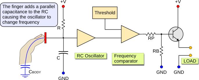
There are basically two ways to make a capacitance touch switch, both based on capacitors (...sure). The first method which is the most popular, is the "Frequency Change". Suppose that you have an oscillator that oscillates at a high frequency (usually 10 to 50 KHz), and uses a capacitor to oscillate. The touch sensor is placed in parallel with this capacitor, or some times the touch sensor is the capacitor itself. If the touch sensor is touched by a finger, then the body capacitance is connected in parallel to the sensor's capacitance. As you may know, the overall capacitance of two capacitors connected in parallel is increased (connecting capacitors), and this causes the oscillating frequency to change (bigger capacitor means lower frequency). Using a digital comparator or any other method to sense this frequency change, one can determine if the touch pad is touched.
Look the following schematic:
The RC oscillator oscillates at a specific frequency, determined by the resistor R and the capacitor C. When the finger touches the touch pad, it adds the capacitance of the body (CBODY) to the capacitor, and this changes the time constant of the RC circuit, changing this way the oscillation frequency. You understand of course thccccccat the capacitor C must be very small. That is because the body capacitance is small as well, usually from 8 to 15 pF. So, the capacitor C must be around this value, so that the body capacitance will have a big influence to the overall capacitance.
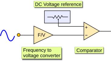
The next stage is the frequency comparator. There are several ways to implement such a circuit. I will explain two of them. The first method, is to convert the frequency into a DC voltage with a Frequency to Voltage converter, and compare it to a fixed DC voltage. This method is widely used in analog applications.
ccccc
Another method that is commonly used in digital applications, is to measure the frequency and compare it with a fixed value. For this method, a time base is needed. Here are the rough steps of such a circuit:
1. Reset the Counter
2. Start the timebase
3. Wait for the timebase to end
4. When timebase ends, read the counter
5. Stop timebase
5. If counter is less than a pre-defined threshold, then the touch is pressed
6. Go to step 1 and repeat
The "Counter" is actually a counter that increases one time on every pulse of the RC oscillator. To understand it, i will give you an example. Suppose that the RC oscillates at 40 KHz when NOT touched, that is 40.000 pulses per second. And suppose also that the timebase is 100 mSec. The counter is usually a 16-bit counter, but this varies according to the design. In our example, it is 16-bits long. Our counter should increase 40.000 times in one second, but our timebase interval is 100 mSec (1/10 second). This means, that our counter will count every time, up to 40000/10 = 4000, and it will then reset. A digital comparator checks if the counter is above a preselected threshold. Let's say that it checks if the counter is above 3950. As long as the counter (at the end of each timebase interval) stays above this value, the output remains low.
Now suppose that someone touches the pad, the C is increased and the oscillating frequency of the RC oscillators falls down to 39.200 Hz (or bellow). The counter now will count instead of 4000, only 3920 (39200/10), which is bellow the 3950 threshold. The digital comparator will notice this change and it will activate the output.
This method is very easy to implement with a microcontroller, but it is rather difficult to make with simple CMOS or TTL chips. That is why the Frequency to Voltage conversion is preferred for simple applications.
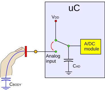
Capacitance touch sensors that work with Capacitive Voltage Divider
This is another very interesting technique to implement a touch sensor. The touch pad is directly connected to the Analog to Digital converter of a microcontroller. Here is a rough diagram of the circuit:
The operation is kinda tricky. All the job is done inside the microcontroller. The steps required to sense a touch are:
1. The ADC module is internally driven to VDD, so that the capacitor used for the A/D conversion is fully charged
2. The analog input (sensor) is internally grounded, so that the sensor is fully discharged
3. The analog input (sensor) is internally disconnected from the ground
4. The ADC module is internally connected to the Analog Input (sensor)
During this 4th step, the internal capacitor will discharge part of its charge to the sensor (or human body). At the end, both capacitors (the internal and the sensor) will have the same voltage across them. This voltage depends on the capacitance of the sensor. If the capacitance is small (eg if the sensor is not touched), then it will absorb only a small amount of charge from the internal capacitor, and the final divided voltage will be slightly less than the initial charge of the internal capacitor. But if the sensor is touched, it will have a larger capacitance, and it will absorb more charge from the internal capacitor. When the voltage is divided, it will be times smaller than the original charge of the internal capacitor.
So, immediately after step 4, the microcontroller starts an analog to digital conversion and reads the ADC module registers. According to the voltage that it reads, it can be determined if the sensor is touched or not. This method is extremely simple to implement with a microcontroller, because the only external part required is the sensor. It is completely improper to implement without a microcontroller. Also, there are some microcontrollers that have different internal switching mechanism, and will not work. As far as i know, almost all PICs with A/D module can be used with this method. For other micros you have to either see the datasheet or just test it and find it out.
@Marc Hello. The 555 solution was not very reliable so i have not post the circuit. It seems though that many people keep asking me for this circuit and i may consider to analyze it one day. Maybe.
And, i'm currently writing the BJT transistor theory. When i finish with this, the next step is the PIC theory... Stay tuned
At 13 December 2013, 12:54:31 user Marc wrote: [reply @ Marc]
Hi,
Very great viedos! Congrats!
I would like to know is you can get us the full schematic layout on the device when using the LN555.
I have a question, what is the power consumption when in hidle?
I also like a lot the architecture using the 2 ADC, but I don't have an experience programing PICs. =/
@reuben Test with separated batteries (not PSU). Maybe it comes from the supply.
At 27 February 2013, 8:07:58 user reuben wrote: [reply @ reuben]
i have encapsulated condenser capsule head in steel basket,and pcb electronics in steel tube,both hardwired to ground...and there was still no reduction in hum. the amplifier is JFET source follower class A,can a class A amplifier hum
@reuben maran First, use shielded wires and make a shielded box. Then, make sure that you are not close to an EMI source like your PC for the tests. My guitar hums if i approach my PC
capacitance question
hello sir,thankyou for your capacitance switch videos. i have a diy condenser microphone with class A JFET amplifier [only one transistor] powered by 48V phantom power from a Behringer Xenyx 802 mixer.
it hums loudly [0dbV] ,but when i grip the ground the hum reduces. i removed the source resistor off the JFET ,so that the amp was dead, and the hum was gone. so i knew it was not produced by the rest of the circuit.
i feel this hum could be produced by capacitance. the circuit in your capacitance switch video,how does one remove the capacitance?i appreciate very much any reply. i have a schematic but not an email address but mine is reuben.maran@gmail.com.
thanks,reuben.
I WILL TRY THIS THEN REPLY U. BUT I REQUIRE HEX CODE FOR PIC MICROCONTROLLER FOR ALL 16 INPUTS. ALSO PL EXPLAIN HOW MAKE 64 INPUTS THROUGH 74HCT573. & HEX CODE PLEASE TO MY MAIL ID: hrd_comfort@yahoo.co.in;
@david Bad news - There must be no galvanic contact between your finger and the foil. Use a thin (3mm) plastic above the sheet - It has to work even with the plastic
At 14 February 2013, 8:12:59 user david wrote: [reply @ david]
hey,
I was building a circuit with the capacitive sensing. I build a touch pad by connecting a wire out of a circuit to a aluminum foil. And the sensor works by directly touch the aluminum foil using your finger.
But then the TA told me direct touch is not really a capacitive sensor, because there's no distance between the two plates. But the circuit works. But according to you, number two method is the direct touch, and the finger is actually a capacitor itself.
@Pedro Sousa for the resistors, you need to make some tests yourself to find the proper values. You can start with RP=220 and RB=22K, which is a good selection.
As for the CMOS solution, you can select for example a quad AND gate (4081). Keep one input H and the other input like the transistor input. Bur i would still stick with the transistor method with SMD transistors
Hi Giorgos,
I'd like to do a panel with 50 Resistance Touch Switches for 5 V DC.
In your video clip you are using a 2N2222 transistor and in the text you say I can instead use a CMOS or other devices.
I'm looking for reliable and cheap switches.
My questions:
1. With 2N2222, what will be the values for RB and RP.
2. If I use a CMOS:
- The circuit is exactly the same?
- Which CMOS should I purchase?
- What will be the values for RB and RP?
- Is it more expensive?
3. For so many buttons, should I use other solution?
Best regards
Pedro
@saravanaeswaran first, you do not need to spam a message in all boards asking the same thing, it is not helpful for other users. You can find similar circuits with capacitance sensors in the "circuits" section of the site:
http://www.pcbheaven.com/circuitpages/
All circuits have complete documentation, schematics and PIC code. If you ask for another variation of a circuit we do not make circuits on demand.
Hi there,
I want to start making a project so I can control a relay with this switch:AC hum touch switches.Can you send me an email with the names of the parts so I can bulid it?Thanks
Hi andrew, this page is only the theory. Go to this page
http://pcbheaven.com/circuitpages/
I have 3-4 circuits with detailed diagrams and explanations.
At 15 February 2011, 5:12:51 user andrew wrote: [reply @ andrew]
thanks for the diagram of the resistance touch switch. I guessed kind of close to the right way but this clears it up. It took me forever to find a diagram! Now if only the resistor values were there...
Manish, i will post a dedicated page for each circuit in the near future. i already began with the resistance touch. follow RSS or twitter to be notified.
At 16 January 2011, 13:15:01 user Manish wrote: [reply @ Manish]
I like the capacitance touch circuit. Can this circuit work in bistable mode using relay for on/Off the appliances. If possible please mail me the part list & schemetic for the same. Thanking u..............

 Home
Home
 Projects
 Experiments
 Circuits
 Theory
 BLOG
BLOG
 PIC Tutorials
 Time for Science
 Contact
 Forum
Forum
 RSS
RSS


 Reddit this

