
|
 Home Home
 Projects Projects
 Experiments Experiments
 Circuits Circuits
 Theory Theory
 BLOG BLOG
 PIC Tutorials PIC Tutorials
 Time for Science Time for Science
|
| ||
|
10 March 2009 Author: Giorgos Lazaridis PWM ModulationIntroduction PWM, or Pulse Width Modulation is a powerful way of controlling analog circuits and systems, using the digital outputs of microprocessors. Defining the term, we can say that PWM is the way we control a digital signal simulating an analog one, by means of altering it's state and frequency of this. The PWM signal This is how a PWM signal would look like: 
 The square wave The PWM is actually a square wave modulated. This modulation infects on the frequency (clock cycle) and the duty cycle of the signal. Both of those parameters will be explained in details later but keep in mind that a PWM signal is characterized from the duty clock and the duty cycle. The amplitude of the signal remains stable during time (except of course from the rising and falling ramps). The clock cycle is measured in Hz and the duty cycle is measured in hundred percent (%). Clock cycle and Duty cycle parameters These are the basic parameters that characterizes a PWM signal. The first parameter, the clock cycle, is easy to understand. It is the frequency of the signal measured in Hz. The other parameter has to do with the switching time of the signal. Take a look in the following three signals: 
All three signals shown above are square wave oscillations modulated as per their oscillation width, so called "duty cycle". They have the same frequency (t1), but they differ on the width of the positive state (t2). The duty cycle is the percentage of the positive state compared to the period of the signal. So:
A 10% dudy cycle means that the positive stated remains positive for 10% of the period of the signal. Example: Suppose that the above signals have a frequency of 1000Hz. This means that their period is 1/1000 => T = 0.001 Sec => T = 1mSec The first signal has 10% duty cycle. This means that during one full period, it remains positive for 10% of the total period:
And this comes to t2 = 0.1mSec. In the first example, the positive state will remain for 0.1 mSec. With the same way we can calculate the t2 (positive state) of the other two signals: Signal 2, 40%: t2 = 40 x 1mSec / 100 = 0.4 mSec Signal 3, 90%: t2 = 90 x 1mSec / 100 = 0.9 mSec Usage of the PWM Find bellow the usages that a PWM can have Voltage and power control One of the most popular usages of PWM is the control of voltage delivered to loads. Those loads could be for example an LED which would utilize a LED dimmer, or a motor that could be a simple DC motor and would be converted into a controlled speed DC motor, as used for example in the modern PC motherboard fans. But how can PWM control the voltage? The idea is simple. A PWM signal with 100% duty cycle would deliver 100% of the voltage. It would be like a DC power supply. But by altering the duty cycle, the result is to reduce the area of the power delivered to the load as shown bellow: 
The total power delivered to the connected load each time, is the area under the positive state of the PWM (the drawn area shown on the above drawing). It is clearly seen that by altering the duty cycle, we can alter the power delivered by the supply. And because the wave form is a square wave, the power supplied each time is calculated by: PDELIVERED = PSUPPLIED x DutyCycle Suppose now that the frequency is high, and at the output of the PWM generator a capacitor is connected like the following schematic: 
Following, you can see the resulting output voltage, when the above circuits operates with duty cycle 10% (left waveforms) and with 90% (right waveforms) 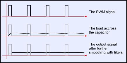 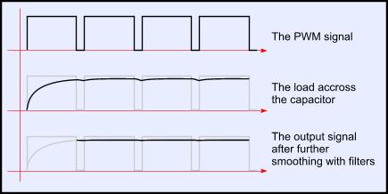 The above example is the principal of the operation for the switching power supplies. Signal transmission Digital signal transmission Very common use of the PWM is the digital data transmission. And because the generation of a PWM signal is easy to be implemented and can also be generated by digital electronics, the data transmission using this modulation is becoming very popular. Here is a simple way to transmit digital data using PWM: 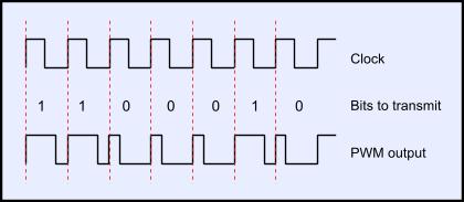
As can be seen from the above time chart, by altering the duty cycle we can distinguish the two different states, 0 and 1. Thus, a 10% duty cycle corresponds to bit 0 and a 90% duty cycle corresponds to bit 1. One of the great advantages using this method is that using two wires as data transmission, we can also produce from those two lines the appropriate power to supply a remote low power drain device! Take a look at the following schematic circuit: 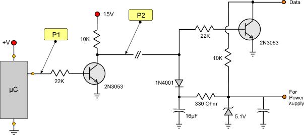
 The logic states of the probe points of the circuit on the left The micro controller will generate the PWM signal with the information as described before. This signal is driven to the base of a switching transistor. This transistor will copy and invert the signal up to 15 volts. This voltage will allow the signal to drive over higher distances through the wire and supply the next device efficiently. The receiver device has another transistor that does exactly the same job as before. Will invert and copy the signal but this time back to 5Volts peak, capable to drive TTL inputs if needed. The whole trick here is the diode with the capacitor. This arrangement will act as the power supply described above, and will produce a smooth DC waveform. The zener diode will stabilize this voltage down to 5.1 volts, capable to supply with power the receiver IC. Analog signal transmission PWM is also widely used to modulate - transmit and demodulate analog signals. The modulation is mainly done using a method called intersective PWM. According to this method, the input analog signal and a sawtooth waveform are driven in a comparator. Each time sawtooth waveform voltage is less than the input signal, the PWM output is driven high and vice-versa. Watch the following drawing: 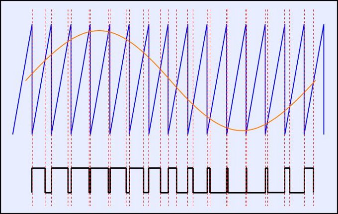
The analog signal (orange) is compared to the sawtooth waveform (blue). The comparator will generate the PWM modulated signal ready to be transmitted. More usages of the PWM Due to the efficiency and simplicity of PWM, as well as the flexibility of this modulation type, there are numbers of applications that it can take place. Using PWM someone can modulate transmit and/or storage analog signals like audio/voice telecommunications and music. Switching power supplies that uses this technology are much more energy efficient than the classic power supplies, reaching up to 60% power saving! The output power and/or voltage can be controlled either digitally using a micro-controller or with the old classic potentiometer. Stepper motors can be easily controlled using PWM, as well as DC motors. The torque and speed of a DC motor can be controlled by altering the voltage or the duty cycle of the PWM easily. PWM is widely used in dimmer circuits that could control a variety of lamps including LEDs. Notice that using PWM, dimmer circuits and other circuits like motor controller that would normally require AC voltage to operate, can be handle with DC voltage directly with no conversion whatsoever. Relative pages Comments
|
|
 Contact Contact
 Forum
Projects
Experiments
Circuits
Theory
BLOG
PIC Tutorials
Time for Science Forum
Projects
Experiments
Circuits
Theory
BLOG
PIC Tutorials
Time for Science
 RSS RSS
Site design: Giorgos Lazaridis © Copyright 2008 Please read the Terms of services and the Privacy policy |


 Reddit this

