
|
 Home Home
 Projects Projects
 Experiments Experiments
 Circuits Circuits
 Theory Theory
 BLOG BLOG
 PIC Tutorials PIC Tutorials
 Time for Science Time for Science
|
| ||
|
22 March 2009 Author: Giorgos Lazaridis The Voltage DividerWhat is the voltage divider The voltage divider is composed (usually) from a set of two resistors in series. The effect of the voltage divider is that it can be used to polarize other components in a circuitry such as transistors or integrated circuits, with a different voltage from the main voltage supply. Thus, a circuit may have 9 volts power supply and using a voltage divider we can supply a transistor in this circuit with 3.6 volts. A typical voltage divider is shown bellow: 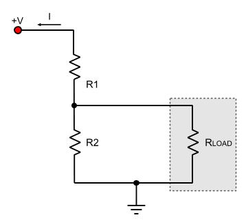
How to calculate the voltage divider The first step to calculate a voltage divider is to know the current that flows within. At first, we will suppose that the RLOAD is not yet connected to the circuit. So using the ohm's law: I = U / RTOTAL => I = U / (R1+R2) (1) The output voltage will be the drop voltage across the edges of R2. Using again the ohm's law we calculate: VR2 = I x R2 (2) (2) because of (1) becomes: VR2 = VOUTPUT = V1 x R2 / (R1 + R2) This is the basic formula to calculate the output voltage of the voltage divider. A major issue here is that R2 is connected in parallel with RLOAD. When you put the voltage divider to work, you should always calculate R2 as RTOTAL with the RLOAD connected in parallel: R2-LOAD TOTAL = (R2 x RLOAD) / (R2 + RLOAD) And replace R2 in the basic formula with the result of the above calculation. Last but not least, is the max current that will be able to go within RLOAD. If we consider the system R1-R2-RLOAD as a mixed resistor connection (series and parallel connection combined), the maximum current I will be less or equal to the current that flows within R1. Thus: I = U / R1 And I = IR2 + IRLOAD An example In the previous example, we want to supply the RLOAD with 3 volts. The input voltage U is 12 Volts. We also want to limit the maximum current that will flow within RLOAD to 300mA. The resistance of RLOAD is 7Ohms. At first we need to calculate the R1. The only thing that is given to us is the current limitation. We suppose that the minimum resistance of RLOAD could be as low as 0 ohms. That would give us the maximum current flow. So, we will calculate R1 in a way that no more than 300mA could flow within: R1 = U / I => R1 = 12V / 300mA => R1 = 40 Ohms Now we need to calculate R2 in a way that the voltage across RLOAD will be the desired one. Using the basic formula from previous calculations: VOUTPUT = V1 x R2 / (R1 + R2)[/B] But R2 is connected in parallel with RLOAD. So we will calculate the basic formula using RTOTAL instead of R2: VOUTPUT = V1 x RTOTAL / (R1 + RTOTAL) => VOUTPUT x (R1 + RTOTAL) = V1 x RTOTAL => VOUTPUT x R1 + VOUTPUT x RTOTAL = V1 x RTOTAL => VOUTPUT x RTOTAL - V1 x RTOTAL = -VOUTPUT x R1 => RTOTAL x (VOUTPUT - V1) = -VOUTPUT x R1 => RTOTAL x (V1 - VOUTPUT) = VOUTPUT x R1 => RTOTAL = (VOUTPUT x R1) / (V1 - VOUTPUT) => RTOTAL = (3 x 40) / (12 - 3) => RTOTAL = 120 / 9 => RTOTAL = 13.3 Ohms =>(approx.) RTOTAL = 14 Ohms Now we come to the final step, to calculate the R2 resistor.The total resistance RTOTAL is calculated from the resistor parallel calculation as follows: 1/RTOTAL = 1/R2 + 1/RLOADsolving for R2: 1/R2 = 1/RTOTAL - 1/RLOAD=> 1/R2 = RLOAD/(RLOADxRTOTAL) - RTOTAL/(RTOTALxRLOAD) => 1/R2 = (RLOAD-RTOTAL) / RLOADxRTOTAL => R2 = RLOADxRTOTAL / (RLOAD-RTOTAL) => R2 = 7 x 14 / (14 - 7) => R2 = 14 Ohms And these are the final values for this circuit to work! Characteristics  Polarizing a transistor The voltage divider is a cheap and easy solution to have different voltages within a circuit with minimal components used. Therefore, it is a very common way for polarizing for example transistors within an amplifier circuit. Nevertheless, a voltage divider can have some major drawbacks. First of all, it is not stable. If the current drawn from RLOAD changes, the voltage across RLOAD will also change. Another drawback is the current limitation. There are usually not resistors with the values required to achieve exactly the desired voltage drop. Many times, higher values of resistors must be used in order to achieve this voltage drop. Typical values are from 330 Ohms, and may go up to 22Kohms or even higher. This will dramatically decrease the maximum current flow from the RLOAD. That is of course not a big deal when polarizing a transistor (as seen on the left side). That is what makes the voltage divider ideal for such kind of applications. Relative pages Comments
|
|
 Contact Contact
 Forum
Projects
Experiments
Circuits
Theory
BLOG
PIC Tutorials
Time for Science Forum
Projects
Experiments
Circuits
Theory
BLOG
PIC Tutorials
Time for Science
 RSS RSS
Site design: Giorgos Lazaridis © Copyright 2008 Please read the Terms of services and the Privacy policy |


 Reddit this

