The process of setting the P, I and D parameters to obtain an ideal response of the system is called tuning. Over the years, several tuning methods have been described, but we will discuss only the Ziegler-Nichols method and of course the manual tuning. The tuning time is relative to the system type and speed of change. If a system has a rapid response, then the tuning time is very short. On the other hand, a slow response system has a very long tuning time. A fast-response system is for example a robot positioning system. An example of a slow response system could be a large water tank heater. It is obvious that a parameter change in the robot positioning system will have an immediate response at the robot's behavior, while a parameter change in the water tank heater system may need several minutes for the systems to react.
Manual PID Tuning
If someone wants to tune a PID system with this method, then he first must be sure that he understands what each parameter does and how each one affects the system, otherwise this can be a headache. These are the steps for this method:
The I and D terms are set to zero
The P term is increased until the system oscillates
The P term is increased slowly to increase the system response, but it must not become unstable
When the P term is set to obtain a desired fast response, the I term is increased to stop the oscillations. This will reduce the steady state error but may increase the overshoot. Faster system response may require some amount of overshoot.
When I is set to desired amount of overshoot and minimal state error, the D term is set until the system achieves an acceptable quick loop to its set-point. Increasing the D term will result in decreasing the overshoot and yields higher gain with stability, but it may cause the system to be very sensitive to noise.
Tuning a PID system with the ZieglerNichols method
The Ziegler-Nichols method was introduced by John G. Ziegler and Nathaniel B. Nichols in the 1940s. To tune a system with the Ziegler-Nichols method, the engineer must first define the critical P gain, which we will name Kc. This is how its done:
The I and D terms are set to zero
The P term is increased until the system oscillates in a stable rate. This will be the Kc
Once the Kc is defined, then the engineer must measure the oscillation period. It is the same like measuring the period of an AC signal. This will be the Pc. Finally, the user can calculate the values for P,I and D parameters using the following table:
Control
P
Ti
Td
P
0.5Kc
-
-
PI
0.45Kc
Pc/1.2
-
PID
0.60Kc
0.5Pc
Pc/8
If you're wondering what the Ti and Td terms are, these are common parameters in a PID controller. A typical PID controller has three parameters, K, Ti and Td, but there are many different kinds of PID controllers. For example, a PID controller with set-point weighting and derivative filter has six parameters K, Ti, Td, Tf , b and c. Parameters b and c are called set-point weights. They have no influence on the response to disturbances but they have a significant influence on the response to set-point changes, so you do not need to worry about them when tuning a PID system.
Example
Here is an example of a system that we want to tune with the Ziegler-Nichols method. First, we need to find the critical P gain. So, we make the I and D parameters zero and we let the controller operate as a simple proportional controller (only P). Then, we start to increase the parameter P and write down the system's response. Here are 4 typical characteristics of a system's response in relation to the P change:
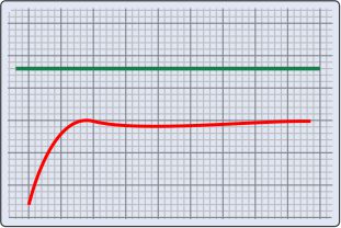
P is too low and must be increased
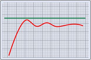
P is still low
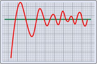
P is too high and made the system unstable
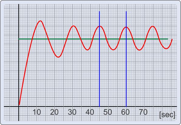
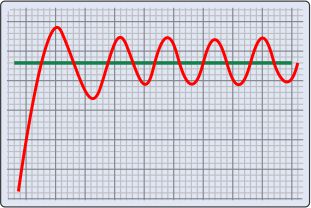
This is the value for P that we are looking for. The system has a stable oscillation.
Suppose that the setting for P is 20. So, Kc is 20. Now we can take a closer look at the last chart:
The horizontal axis shows the time in seconds. As you can see, the oscillation has a period of about 15 seconds (45 to 60 seconds). So, the second parameter that we need, the Pc, is 15''. To get the PID parameters for our controller, we need to use these values with the Ziegler-Nichols table:
@Saimul If there is no oscillation then maybe you don't need a PID controller. Does it get unstable if you increase Kp too much? Is there a steady-state error?
I'm also trying build PID controller to control temperature of heater. Heater heat the metal plate.
Till this time:
Heater is about 500W, and i trying control temperature by the triac. Heater is less frequently ON, if temperature is closer to the temperature that we want to achieve (set to 100deg.C). In this algorithm heater is on in duty from 10% do 100%. The best result is when:
- duty=100% for T<70deg.C
- duty=80% for T=71 to 80deg.C
- duty=60% for T=81 to 90deg.C
- duty=50% for T=91 to 100deg.C
- when T>=100deg.C then heater is OFF
In algorithm above temperature oscillates in about /- 3deg.C
And that way I would like to implement PID controller.
So for example if sum from calculating PID will be lets say from -50 to 120 then for my duty from 0 to 100% i must convert PID to range 0-100 so:
PID=-50 to 120
DUTY=PID 50
DUTY=0 to 170
DUTY=DUTY/1.7
Is that correct translation ?
At 13 February 2014, 13:45:08 user Saimul wrote: [reply @ Saimul]
Hi...I am working with a development of PID controller for a water heater. The problem that I am facing right now in determining the value of Kp,Ki and Kd. If I want to use Ziegler-Nicholas method for tuning PID then I have to determine the critical gain Kc and oscillation period Pc. After I can calculate PID parameters accordingly. But the problem is there is no oscillation in my system. So what should I do now?
@sierra It largely depends on your application. If you have an 8-bit then you have to limit it from 0 to 255, or if you need negative numbers you limit to 127. So you have to do the proper divisions when you read the input to fit these ranges. Which means that you have to know before hands the minimum and maximum values that the sensor will send you
At 13 November 2013, 16:53:09 user sierra wrote: [reply @ sierra]
Hi,
Nice work, thank you.
When you calculate the P_Out value it may be too large or too small (negative). In such a case you may have to limit the maximum P_Out value. How do you determine the minimum and maximum P_Out value.
@Pushkin2023 fot Ti and Td i'd say the faster the better, depending on the response of the system (you want very quick response). As for the D term, do not reset it to zero, it will reset itself in a couple of Td times...
Very nice tutorial. I'm trying to make a pid controller for my rotary inverted pendulum. I'm doing the pid computing every 20ms (timer2 interrupt, sets a flag in main loop), how should be Ti and Td?(how many times greater then pid loop) Another thing: the d_term and i_term shouldn't be reseted to 0 when the error is 0 or very very close to 0 ?
Morning
Thank you very much
I was wondering how to adjust the set point and can I program it using flowcode mplab from microchip? If not what ic and program should I use ?
@NOAK an 8-bit number can measure from 0 to 255 with integer numbers. So, it fully covers the range 0 to 100. But it cannot measure from 0 to 600 with 1 degree accuracy... Maybe with 3 degrees accuracy (because 3*256=768)
At 24 August 2012, 11:12:34 user NOAK wrote: [reply @ NOAK]
"For example, a temperature controller that is used for a system which measures temperatures from 0 to 100 degrees with 1oC accuracy can be implemented with 8-bit registers, But if the system measures from 0 to 600oC then the 8-bits are just not enough."
could u explain why 8-bit MCU is not enough for 0-600 C application?
for example , i want to control a servo motor to move it to a commanded position and the output of the control system is PWM . so i should select proper P,I & D values so that the summation , i.e PID , is the correct PWM output which makes the motor move to the commanded position regardless to what degree the PWM should be propotional to the PID vlaue .
@akshay That is the idea. You make all these calculations to come up with an output power that is required. This output can b anything, like an analog voltage, an angle of a servomotor, a throttle position of an engine.... anything.
@akshay now this depends on the control circuit. If it is PWM for example, you can change the duty cycle depending on the value you calculate... e.g. 0-100% duty cycle = 0 - 500 calculated PID
Or if it has an analog output... you can change the analog value...
... it is 8 pages long! Filled with in-depth description and pictures the developmental changes to his code. And it is linked to the Arduino Playground code library, along with an Autotune library, at:
http://arduino.cc/playground/Main/LibraryList
in the Input / Output subcategory.
Finally, the author links to the site of his own mentor, at:
http://controlguru.com/
I have not yet looked at this myself, but I hope to find it educational.
@Artur the idea of the It and Dt time parameters, is to avoid an overflow. The I parameter for example is used to have usually small changes, so that the operator can balance the immediate changes of the P parameter. If the I builds up on every cycle, then it will become huge very fast, and the system will not become stable. The idea is that the I build up slowly, and the system becomes stable slowly. The delay depends on the system's response. If a systems responses fast (for example hot air blower) then the It is small, otherwise (eg large water tank heater) It may be very large. Same stands for D.
The parameter P follows the changes in output, it reads the error and changes the power accordingly in every cycle. The parameter I builds up slowly. Here is how we use to explain these parameters.
P is the present, it looks at the output and changes with the present error.
I is the past, it looks at the past errors and changes accordingly.
D is the future, every Dt it looks at the error and according to the rate of change it tries to predict the future
I am not sure what the result of the ring buffer would be. It sounds as a good idea, since the errors some 100 cycles before (for example) are not important for the I term. If i make another PID controller, i will experiment with this idea.
At 26 January 2012, 21:34:05 user Artur wrote: [reply @ Artur]
I agree with others: best explanation I've seen so far. I'm wondering, would it be a good idea to store error in a ring buffer, e.g. 16 last values and calculate I and D from that on every iteration? If not then why. Other than the obvious added CPU cost.This way I would follow changes in output, not change incrementally every Ti cycles. Also why not calculate D in every loop based on previous loop's error?
@Bill Kostelidis regarding the Integral, if you calculate it in every cycle, the system will never be stable, unless the system is highly reactive. That is exactly the point of the integral term existence after all: to check the progress between time intervals and decide if needs more or less power.
To use the result of the PID, you need first to scale it to an easy-usable number. I use for example -127 to +127 which is one byte. The, you can either translate the number to 0-256 or just use it as is. Finally, you need to have a variable output. If the output is for example PWM, then i would translate the PID result to 0-256. Then, i would use this number as a PID duty cycle (0-0% 256=100%).
I really like your projects. Although I have my disagreements with the way that the Integral is not calculated in every circle, since it is working, you must be correct!
I am working in a PID project myself and I have a question, if you can help, it's great.
I am heating water with immersion heaters, resistors. They are plugged directly in 220 Volts but I will use PWM to control them. The control is going to come from my PID.
After I get the output from my PID controller, how am I going to translate it to PWM? I mean, if the output of my PID indicates 2 Celsius degrees down, how am I going to say to my PWM to adjust to 2 degrees down?
I am going to work experimentally at first, but I am searching to find a more solid solution, any ideas?
Thanks,
Bill.
At 27 October 2011, 4:01:13 user sorin wrote: [reply @ sorin]
I am a Vietnamese. I have read many textbooks about PID control in some subjects in university, but I've never really understood the meaning of this method, I think the theory is explained too complicatedly than what it really means.
This post is a great explanation! I understood it easy.
Thank you very much!
At 30 September 2011, 16:20:54 user Erik T wrote: [reply @ Erik T]
This IS the best explanation of PID I have ever seen.
The historical background adds so much to the explanation,
that it makes so much more sense.
I'd like to know how you created the graphs!
I think a graphical demonstration program of PID would be awesome.
It could allow users to set parameters and watch and compare settings.
It could then show how to tune PID, using either method or both.
I have retuned repaired PID controllers for CNC equipment, and until
now have never understood why the directions for tuning were what they
were. "... then reduce these two levels, and then turn this third one up until the machine oscillates." It all makes sense now.
thank you, I look forward to coding something like the demo program
because I cannot find one.

 Home
Home
 Projects
 Experiments
 Circuits
 Theory
 BLOG
BLOG
 PIC Tutorials
 Time for Science
 Contact
 Forum
Forum
 RSS
RSS


 Reddit this

