
|
 Home Home
 Projects Projects
 Experiments Experiments
 Circuits Circuits
 Theory Theory
 BLOG BLOG
 PIC Tutorials PIC Tutorials
 Time for Science Time for Science
|
| ||
|
23 March 2010 Author: Giorgos Lazaridis Simple Ways to Make Fans SilentFrom time to time, i have publish circuits to control a DC fan speed. Other circuits change the voltage that powers the fan, others use PWM to control it. Some use only discrete components, some others use microcontrollers. Some are easy to implement, some are harder. While i was absorbed in the complexity of more advanced circuits, suddenly i saw light! "Hey, why not presenting the easiest method EVER of reducing the RPM speed of a fan"? I think that there are many people out there that will love this method, as it is easy, cheap - cheaper than you can think - and yet it works! Moreover, it needs of NO circuit board or other complicated staff! The basic idea Well, the basic idea is that, a DC fan's rotation speed depends -among other characteristics- on the voltage that the fan is powered. Lower voltage will cause the fan to draw less current ( I = U / R ). Less current generates weaker magnetic field. Weaker magnetic field produces less torque on the shaft. Less torque on the shaft means simply less rpm! But first, let's see the circuit that will follow in action: How can someone reduce the voltage? No! I will hold my self! Although i am seduced by the idea that i can extend this paragraph to pages, i will only explain -as promised- the easiest way to do it. In a word, this way is called "Resistor"!. The only thing that has to be done, is to connect a resistor in series with the power supply of the fan. The resistor will cause a voltage drop across its leads. This voltage drop will be subtracted from the overall voltage on the fan, and therefore the voltage across the fan will be reduced. If you read the theory about connecting resistors, you can see that a resistor will cause a voltage drop across its leads and can be calculated as follows: U = R x I Where R is the resistor value in ohms, and I the current that flows through the resistor. Now, it is not THAT easy to calculate the resistor that you need for your fan. That is because each fan has completely different characteristics. For example, other fans draw 290mA, others 400mA, others 120mA. Some fans can operate with lower voltages down to 5 volts, others down to 6volts, others down to 7 volts. Bellow these voltages they may stall. I really, really discourage you trying to figure out the fan characteristics and calculate the resistor value. Instead, i encourage you to get a set of resistors between 10 and 100 ohms and try each one. After all, each one will not cost more than $0.20. Be careful with the resistor wattage!!! Before you go and get your resistors, you need to know this. There are resistors from 1/8 watt up to several watts. Your resistor must be able to dissipate the amount of power that needs, otherwise it will be burned. Again, there is a proper formula to calculate the wattage: P = V x I Where P is the wattage, V the voltage drop and I the current. For example, if you want to operate your fan at 7 volts, that is 5 volts less than the power supply (12V),and you want to provide max current 200mA, you need the following resistor: R = V / I = 5 / 0.2 = 25 Ohms P = V x I = 5 x 0.4 = 1 Watt Now what? You will go and ask of a resistor 25 Ohms 1 Watt? NO! First of all, you will not find such a resistor. The resistor values are standard (you can find the resistor standard values here). And also, 1 Watt is the lower limit. So... CONCLUSION:Provide yourself a batch of resistors between 10 and 100 Ohms, ALL rated at 5 Watts. Maybe 2 watts are also enough. This is something that you have to find it out yourself. If you are asked about the tolerance, just answer "5% is ok!". If you do not want to look "completely noob", here are some resistor values that DO exist: 10, 12, 15, 18, 22, 27, 33, 39, 47, 56, 68, 82 and 100 Ohms, all rated at 2 and 5 Watts with tolerance 5%. I would suggest you try with 12 Ohms, 22 Ohms, 33 Ohms, 56 Ohms and 82 Ohms. But do NOT rush. Read the following article as more interesting ideas are yet to follow. And how am i going to connect this resistor??? In series of course! Well, each fan comes with 2 or 3 wires. There are also the modern PWM fans that have 4 wires. We will not discuss about them though. So, in each case, there should be a RED wire. This is the POSITIVE power supply of the fan, and this is the one that you have to chop. If there is no red wire, then you have probably a 3-wire fan. In this case, the POSITIVE wire is the middle one. The resistor must be placed on this wire. For this reason, you need to cut the positive wire and solder the two ends of the resistor in each side. Remember to use heat-shrink tubes! You don't want your nice motherboard to be short-circuited with +12 volts do you?
Some brands comes with a pre-made resistor kit. Two molex connectors are bypassed between the fan connector and the motherboard connector. The positive wire between these molexes is cut and a resistor is connected in series. No difference than before, yet easier to install:
So what? My fan will be lazy for the rest of it's life? Ehmmmm, if you stop here, the answer is YES. But there is a better way. You can solder a simple switch parallel to the resistor. When the switch is open, the current will go through the resistor and the fan will rotate at low speed. But when the switch is closed, the current will follow the "easiest" way, the one with the less resistance, and that is through the switch! The voltage drop across the resistor is almost zero (theoretically it is zero). The fan will then rotate at full speed! So, you can simply have 2 wires soldered parallel to the resistor and a selector switch in front of your PC case. With the switch you select the "Turtle" or the "Rabbit" speed! So simple!
This is the final "circuit" that you will have! 
Circuit Ideas Admit it, it was too easy! I should include some other circuits more advanced! Actually, what i have in mind, is... The easiest way to have adjustable speeds in a DC fanI have tried, and i will show you 3 circuits that does the same thing: Providing more than one speed selection of a DC motor. All circuits use a switch with multiple positions. I will start with the simplest: Multiple speed selection circuit for DC motors using resistorsWatch a video of the circuit Once again, this circuit will use ONLY resistors. The idea is similar to the first circuit described with the resistor. But now, i will use several "small" resistors in series. When you connect resistors in series, the total resistance is the sum of each resistor value. Thus, if i connect 8 resistors each one 10 ohms, i will have a total resistance of 80 Ohms. And now comes the tricky part: I will use a rotary selector with 4 positions. Each position, is connected in a different node of the resistors. For example, the first position of the switch will be connected at the end of the resistor series. The second will be connected between the 6th and the 7th resistor node, the third between the 3rd and the 4th, and the last will be connected on the first resistor, directly on the positive wire. The schematic diagram is as follows: 
As you can see, the 4-positions selector each time uses a different number of resistors. On the first position (most right), all resistors takes part. On the second position, 6 resistors takes part. On the third position 3 resistors takes part and on the last position there is no resistor connected. The more the resistors that takes part, the more the voltage drop generated, thus the less the speed of the motor. You can use a selector with more positions for more speed adjustments. As for the resistor wattage, here comes the good news. The wattage of each resistor, is the result of the total power divided by the number of the resistors. But be careful! If for example the total wattage is 2 watts, this does NOT mean that each resistor can be 2/8 = 0.250 Watts!No! Because when the selector is on the 2nd position, only 3 resistors are used, and they should be 2/3 = 0.66 Watts! I suggest, you have the first 4 resistors 1 Watt, and all others 1/2 Watt. You could have for simplicity all resistors rated 1 Watt as well! No problem. It all depends on the current that the motor will draw and the voltage reduction. For example, my fan that is small and draws only 290 mAmps, runs with no problem having all the resistors rated 1/2 Watt. I NEVER use less than 3 resistors in series though! Multiple speed selection circuit for DC motors using diodes Watch a video of the circuit My favorite! This method works exactly like the previous one - with the resistors. A number of diodes are connected in series. Each diode has about 0.8 Volts voltage drop across its leads. 10 diodes for example would create 8 volts voltage drop. This method is much more power-efficient than using resistors, as diodes do not generate too much heat as the resistors. Moreover, it is easier than the resistors to calculate the total voltage drop, when you know the drop of each diode. I use for example the 1N4001 that have (according to the datasheet) typical voltage drop around 0.93 Volts. No matter which fan i use, the total voltage drop will be the same. You should pay attention when connecting the diodes. Unlike the resistors, diodes have polarity! There is a strip near one end of the diode. This strip indicates the cathode of the diode. The diode is properly connected (forward biased), when the anode (the other end) is connected to the positive of the power supply and the cathode is connected to the negative. A reverse biased resistor will not allow any current to flow within, until the break point where the diode is destroyed. 
The method with the diodes is by far better than the resistors. With the diodes you can have more steps of speeds and they are more stable and power efficient. Also, the 1N series can handle up to 1A current. For a PC fan, the 1N4001 diode is perfect, and almost have the same price as the resistors. Almost. But it worth its weight. Multiple speed selection circuit for DC motors using Zener diodes Watch a video of the circuit I don't really like this method. it is expensive and you cannot have many speed steps. But a circuit with 2 speeds (+ full speed) can be very easily implemented. Moreover, a circuit like the first one (with the single resistor and the switch) would be more efficient and more stable if a Zener diode had been used instead. A 5 Watts Zenner may cost up to $1. A Zener diode is a remarkable component. If a Zener diode is reverse biased, it will generate a very specific voltage drop across its leads. This voltage drop is pre-defined and is fixed, no matter how much current goes through. There is of course a power limitation for Zener diodes. For PC fans, you need to consider 5 Watts Zener diodes and not less! Even a small fan that draws 300 mA, will need 3.6 Watts! The circuit that i tested had 2 Zener diodes with voltage drop 3.9 Volts each. I am not sure, but i think that there are no Zener diodes rated up to 5 Watts with smaller voltage drop. This is a major disadvantage if you want many speed selections. It is impossible. If you connect for example 3 Zener diodes in series and each one has 3.9 voltage drop, then the fan will stall as the voltage drop overall is too much (11.7). Finally, pay attention when connecting Zener diodes. They MUST BE CONNECTED REVERSE! Like simple diodes, Zener diodes have also a small strip to indicate the cathode. But unlike simple diodes, the cathode MUST BE CONNECTED TO THE POSITIVE!!! Otherwise the diode will be immediately and irreversibly damaged. 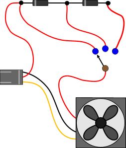
Relative pages Comments
|
|
 Contact Contact
 Forum
Projects
Experiments
Circuits
Theory
BLOG
PIC Tutorials
Time for Science Forum
Projects
Experiments
Circuits
Theory
BLOG
PIC Tutorials
Time for Science
 RSS RSS
Site design: Giorgos Lazaridis © Copyright 2008 Please read the Terms of services and the Privacy policy |


 Reddit this

