The circuit assembled on a breadboard during the tests
This circuit is mostly for exercising and fun. I do not think that someone could ever exchange ye old plastic cubes with a cold electronic dice to play backgammon... But still, this is an interesting circuit.
The Circuit
The circuit is a 4017 decimal counter. 6 outputs are used to drive the transistor LEDs. The LEDs are connected in three pairs and a single LED. The clock pulses comes from the 555 timer. All the time, the 555 is out of voltage. The clock input is then pulled up using the R3 resistor. When the button is pressed, the 555 is connected to power and delivers pulses to the 4017. The dice is then 'rolled' until the button is released and the 555 stops sending pulses.
This circuit can operate with any voltage from 5 to 15 volts. The only thing that needs to be changes is the limiting resistor of the LEDs, R4 through R10. The value must be calculated according ti the voltage. This circuit is designed for 5 volts. You can use the Dr.Calculus LED resistor calculator to find the resistor needed for your application.
The LED array
What you may have already notice, is that the LEDs are not driven directly each one. Instead, they come in pairs, except one LED. This is done in purpose to reduce the diodes and the transistors used to drive them. I will try to explain what is going on.
First of all, the CO (Carry Out) output. This output remains HIGH from number 0 to number 4. This output is used to light the bottom left and top-right LEDs. So, when the output 0 of the 4017 is HIGH, the only LEDs that lights are those two, because output 0 drives NO LED. So, number 2 is indicated.
Onto the next number now. Output 1 of the 4017 drives the middle LED. Along with the bottom-left and top-right LEDs (from the CO output), number 3 is indicated.
The next output #2 is HIGH. This output drives the top-left and bottom right LEDs. Along with the two LEDs form OE output, the number 4 is indicated.
Following is output #3. This will drive the middle LED, as well as the top-left and bottom-right LEDs. Along with the 2 LEDs from the OE, number 5 is indicated.
Then, number #4 output is HIGH. this output will turn on the top-left and bottom-right LED, as well as the middle-left and middle-right LEDs. Along with the two LEDs from OE, number 6 is indicated.
For the following numbers, the OE output is turned off. So the bottom left and top-right LEDs are turned off. The output #5 will turn on the middle LED, and thus the number 1 is indicated.
Until now, all numbers 1 through 6 are indicated. On the next clock pulse, the output #6 will become High. But this output controls the RESET of the 4017. So, the chip will immediately reset and the count will re-start from output number 0.
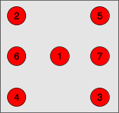
This is how you should place the LEDs according to their numbers:
Bill Of Materials
Resistors
R1
Resistor 470 Ohm 1/4 Watt 5% Carbon Film
R2
Resistor 470 Ohm 1/4 Watt 5% Carbon Film
R3
Resistor 22 KOhm 1/4 Watt 5% Carbon Film
R4-10
Resistor 220 Ohm 1/4 Watt 5% Carbon Film
R11-14
Resistor 4.7 KOhm 1/4 Watt 5% Carbon Film
Capacitors
C1
10uF 16V Electrolytic Capacitor
Diodes
D1-6
1N4148 Switching Diode
LED1-7
LED 3mm red
Transistors
T1-4
BC547 Switching and Applications NPN Epitaxial Transistor
I've tested your circuit on YENKA. The wires and components are similar to the circuit picture however the decade counter keeps exploding and also I have put the resistor values correctly. However, the decade counter keeps exploding. What can I do to fix it?
@Kalung it seems that you have a wrong connection or something is dead...
At 24 December 2011, 12:10:45 user Kalung wrote: [reply @ Kalung]
Hey.
awesome curcuit, fun to make, and a fun project.
I just got 1 problem, when i turn on the power LED 6 1 7 keep being turned on, and when i press start, LED 4 3 works, but LED 2 5 is off all the time.
when im takeing an control it seems like LED 6 7 get power from R7 and R8.
1 thing i dont understand, first i forgot the power on the transistors, and it actully allmost worked, only 2 LED didnt work, becuase i forgot to connect them, after i connected them, and connected transistorene, it keep makeing problems for me, and this is were im standing rigt now.
srry for my bad english, hope you can understand, what i wrote
@Amanda what happens when you remove the 555 from the circuit completely? Either the 555 is defective, or (most probably) you forgot to connect the R3 to VDD...
i have tried making this circuit.but in my circuit all the 7 LEDs glow at all times irrespective of whether the push button is pressed or not...i have used 555p ic for timing,i guess there is some problem with the timer.i need help on this please.
Ta LED pou anefera parakatw de syndeontai me tis antistaseis twn 4,7KOhm alla me aytes twn 220. Akomh, yparxei problhma ean anti gia 3 mm Led na xrhsimopoihsw 5 mm? Epishs, kata la8os anti gia 220 Ohm evala 100 Ohm. Peirazei?
Sorry pou to xanagrafw alla nomiza pws mporousa na xrhsimopoihsw ellhnikous xarakthres.
Egw to dokimasa to kuklwma, alla exw tis ekshs apories kai ta parakatw provlhmata. PRWTON, uparxei diafora metaksu switcing diodo kai kanonikhs? DEUTERON, to diko mou de leitourgei sta 5V alla sta 9V. TRITON, molis to sundew de sumvainei tipota, alla otan pataw to mpouton ta LED anavosvhnoun etsi opws 8a eprepe, parathrhsa omws oti duo ap' auta (ta opoia argotera sundeontai metaksu tous mesw twn antistasewn twn 4,7KW) menoun sunexws anamena. Mporei veveia na anavosvhnoun toso grhgora pou den to katalavainw! Oi sundeseis einai oles swstes (polakis elegmenes)kai tipota den einai kammeno. Mallon kati den paei kala ston tropo pou sundesa ta plhn kai ta sun. I N E E D H E L P !
At 24 March 2011, 7:55:51 user Fung wrote: [reply @ Fung]
Known that a LM358 with some parts provide a slow-down function (I have this). But how can I add a slow-down function without replacing the 555 timer or changing a lot of the circuit?
elengr, diodes are used to avoid current flow back to an output from another output. Transistors are used to amplify current so they can drive the LEDs.
elendr, the diodes are used to prevent HIGH voltage from an output to go to another output that has LOW. For example, suppose that Q1 is HIGH to light the LED1, but Q5 is LOW. If D1 was missing from the circuit, then what happens is that Q1 that is HIGH is directly connected to Q5 that is LOW, and maximum current will flow, destroying instantly both outputs.
As for the LEDs, most probably you got a wrong connection. If you want more help, join the forum and start a thread to post images from your circuit
Yes indeed there is one. I put this for my power supply sparks. I do not list it because the 5volts that the circuit is supplied, are supposed to be smooth and free of parasitic noise. This is a 1uF capacitor (i suppose). If you power by battery or a good power supply, can be totally omitted.
No, not really. But, imagine that someone tells the numbers from 1 to 6, about 5000 times per second... And when you say STOP (release the button), he tells you the number he is counting at this very moment... It is pretty much random in a way.

 Home
Home
 Projects
 Experiments
 Circuits
 Theory
 BLOG
BLOG
 PIC Tutorials
 Time for Science


 Contact
 Forum
Forum
 RSS
RSS


 Reddit this

