
|
 Home Home
 Projects Projects
 Experiments Experiments
 Circuits Circuits
 Theory Theory
 BLOG BLOG
 PIC Tutorials PIC Tutorials
 Time for Science Time for Science
|
| ||
|
12 August 2010 Author: Giorgos Lazaridis Fixed Countdown Timer For -Geek- GamersIn some games, speed and fast reaction is the key to win. There are situations where an action must be carried out every certain amount of time. For example, in Men Of War (which is my favorite game), the Sturmtiger and the Panzerwerfer as well as many other artillery pieces require 180 seconds to reload, and in the heat of battle you may simply... forget them! Or you may keep on checking them (and waste your time) if the loading is completed. The circuit that i present here is a fixed time countdown timer, that i plan to embed in my Men Of War Game Console that i currently make. It will countdown 180 seconds, and it will inform the player with visual (LED) and acoustic (buzzer) means. It can be used of course for other purposes like in PCB UV transfer cabinets or timer for boiling eggs :). The time can be changed to any fixed value of course. The Circuit I really love choosing the most suitable PIC for the job. This is sometimes rather frustrating, for i need to have a big stock of different PICs, which for me is just impossible. For this application i chose the junior 12F519, which is provided by microchip mainly for RTCs. Here is the schematic diagram of the circuit: 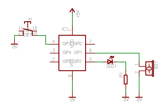
The operation is as follows: By clicking the pushbutton, the PIC will start the countdown. The LED will then start to flash in a slow rate, indicating that the countdown has begun. There are 4 checkpoints (declared as variables). In the firmware that i have here, these checkpoints are 120'', 60'', 30'' and 10''. When the countdown goes bellow a checkpoint, then the LED blinks faster. In the firmware that i have upload, the flash interval values are as follows: When the countdown reaches the 3rd checkpoint, then the buzzer will beep once to inform the gamer. Bellow the 4th checkpoint, the buzzer will beep every second to prepare the gamer for action. Upon countdown end, the buzzer will beep continuously for 2 seconds. Afterwards, the LED will be turned off and the circuit will be ready for another button press During countdown, the gamer is able to reset the operation, by pressing the button for a period of time. If he do so, a distinctive 'beep' will sound from the buzzer and the circuit will reset. Upon next button click, the countdown will restart from the beginning (180'' countdown). The PIC firmware Here is the latest firmware for the PIC. First, the assembly listing for re-compiling:
And the hex file if you only want to upload it on a PIC directly:
Changing the countdown time I have all the parameters required in the 'Constants' section in the assembly listing. There is one parameter named 'GLTime1'. This is the countdown time. As you understand, the PIC is 8-bit and so is this parameter, so the interval can be from 1 second up to 255'' (binary 11111111). If for example you want 60'' countdown time, then you only need to change this value to 60 (GLTime1=d'60'). If you want to increase the countdown time to more than 255 seconds, then you need to make a trick in the assembly listing. Within the listing, you will find this code: Mainloop call Wait10mSec call Wait10mSec btfss Beeper_Long bcf Beeper call Wait10mSec call Wait10mSec call Wait10mSec If you add up the 'call Wait10mSec' lines, you will find out that it makes a total of 50msec time interval. That is because this cycle runs 20 times per second. So, to increase the countdown interval, you only need to add more 'call Wait10mSec' underneath them. I suggest you add every time 50 msec (5 times 'call Wait10mSec') to have an even number of divisions for the GLTime1 parameter. Let's see an example. Suppose that someone wants to have [P]10 minutes countdown time. That is 600 seconds (60x10). Originally this firmware can count up to 256 seconds. So we need to triple this amount of time (256 X 3 = 768 seconds max). We need therefore to triple the delay routine! Originally, this delay routine is (as described above) 50msec. I need to add 100 msec delay more, to have 150msec of delay. To do so, i need to add 10 times the 'call Wait10mSec' line. So, the code will be as follows:[/P]Mainloop call Wait10mSec call Wait10mSec btfss Beeper_Long bcf Beeper call Wait10mSec call Wait10mSec call Wait10mSec ;Here i add my 100msec of delay call Wait10mSec call Wait10mSec call Wait10mSec call Wait10mSec call Wait10mSec call Wait10mSec call Wait10mSec call Wait10mSec call Wait10mSec call Wait10mSec Now, the value in the GLTime1 parameter will be tripled! So, for the 600 seconds of delay, i need to make this parameter 600/3 = 200. So, i change this line to: Mainloop ; Conastants -------------------------------------------------------------- GLTime1 = d'200' You can of course change the code a little bit to make it more elegant. For example, you can make a loop as follows: Mainloop call Wait10mSec call Wait10mSec btfss Beeper_Long bcf Beeper call Wait10mSec call Wait10mSec call Wait10mSec ;Here i add my 100msec of delay movlw d'10' ;10 times loop movwf MyLoopCounter ;A register that has to be added in the RAM preserved section call Wait10mSec decfsz MyLoopCounter goto $-2 Remember to change the other parameters, for they will be tripled as well. These parameters are: GLFlashInt = d'20' GL1FlashInt = d'15' GL2FlashInt = d'12' GL3FlashInt = d'3' GL4FlashInt = d'1' GL1FlashTime = d'120' GL2FlashTime = d'60' GL3FlashTime = d'30' GL4FlashTime = d'10' TimeEndBeepDelay = d'2' Is there an easier way to change the maximum countdown time? Well, yes there is an easier way than the one previously described. Within the code, you will find this line: Mainloop incf miliCount,f movlw d'20' subwf miliCount,w We will focus at line "movlw d'20'". This is the multiplier of the delay as described above. Originally, the delay is 50msec, multiplied by 20 makes one second (20*50 = 1000 msec). So, every unit of the parameter GLTime1 corresponds to 1 second delay. That can be easily changed by increasing the number of the multiplier. If for example you write "movlw d'40'", then each unit in the GLTime1 parameter will correspond to 40*50 = 2000 msec, or 2 seconds! That simple!. This method has a slight drawback. It has a limitation! The maximum value for the multiplier is 255 (8-bit). So, the maximum delay is 255*50 = 12750 msec per unit, and if the parameter GLTime1 is also 255, then the max delay to be achieved is 12750*255 = 3251250 msec= 3251.25 seconds which is approximately 54 minutes. If for any reason this value covers your needs, then i strongly suggest you use this method to increase the maximum time! Here is a table with some values that you can use for the multiplier:
Here is a real life example. Suppose that again we want a 10 minutes countdown timer. That is 600 seconds. From the above table we choose the 3rd row that has maximum count up to 765 seconds. So, the multiplier must be 60, as indicated from the first column of this row. That is the first change: Mainloop incf miliCount,f movlw d'60' subwf miliCount,w Finally, from the second column of this row, we see that each unit of the GLTime1 parameter corresponds to 3 seconds. So, to achieve 600 seconds of delay, we need to make GLTime1 to 600/3 = 200: Mainloop ; Conastants -------------------------------------------------------------- GLTime1 = d'200' And that is the second and last change. Again, remember to change the other parameters as in the previous method. Bill Of Materials
Comments
|
| |||||||||||||||||||||||||||||||||||||||||||||||||||||||||||||||||||||||||||||||||||||||
 Contact Contact
 Forum
Projects
Experiments
Circuits
Theory
BLOG
PIC Tutorials
Time for Science Forum
Projects
Experiments
Circuits
Theory
BLOG
PIC Tutorials
Time for Science
 RSS RSS
Site design: Giorgos Lazaridis © Copyright 2008 Please read the Terms of services and the Privacy policy |

 Countdown Timer For Gamers - Assembly listing - V 1.0


 Reddit this

