
|
 Home Home
 Projects Projects
 Experiments Experiments
 Circuits Circuits
 Theory Theory
 BLOG BLOG
 PIC Tutorials PIC Tutorials
 Time for Science Time for Science
|
| ||
|
13 April 2010 Author: Giorgos Lazaridis How Thermocouples (TCs) WorkSome solutions to this problem The Ice Bath Reference Any thermocouple pair, when is at 0oC, will generate no EMF! So, by simply connecting the wires inside an ice bath, the readings from the K-junction are not altered! 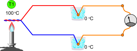
Double Oven Reference Two ovens are used to simulate the ice point reference. The wires of the thermocouple are joined in opposite polarization inside one oven, and then are connected with the copper wires to the other oven. By having different temperatures inside the ovens, the ice point reference can be simulated. 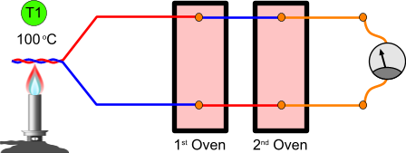
Out of the lab door - The Isothermal Block  A K-Type thermocouple with the copper junction inside an isothermal block The above methods are valid and will return correct results. Yet, they are very difficult to be used in real life applications. Imagine for example, an automation in a machine to measure the temperature with a thermocouple. You will need a thermocouple, a display, a refrigerator or two ovens.... Therefore, other methods have been invented to compensate the reference temperature. But before i explain these methods, i need to explain first the isothermal block. In environments where the temperature may vary from point to point, like the engine room of a ship, there may be situations where the connectors of the measuring equipment will not have the same temperature, even if they are just 2-3 cm away. Therefore, we need to ensure that bot junctions will be at the same temperature. For this reason, the isothermal blocks are used. The simplest isothermal blocks are covers made of special material usually enclosed in plastic housing. Inside there are the thermocouple-to-copper junctions. The special material will ensure, that both junctions are kept under the same temperature, very important in some situations. Some other isothermal blocks are more advanced, with multiple thermocouple wire inputs and with extra analog signal with the junction reference temperature, used for software compensation (as we will discuss later on). Hardware compensation This is a very common method to compensate the temperature at the copper junction of the thermocouple, also called "Electronic Ice Point Reference". According to this method, a thermistor is placed inside the isothermal block. The thermistor resistance will change according to the temperature inside the isothermal block. Using a DC voltage and a couple of resistors to control the gain, the circuit will add the voltage needed for the specific temperature inside the isothermal block! The reason why this method is very popular is because the isothermal block is rather cheap, while it saves a lot of computing time and effort to calculate the temperature. This way, it is possible for a PLC for example to retrieve much more readings from different points faster. Yet there is a drawback to this. The major drawback is that for each thermocouple, a different hardware compensation must be used. This will increase the space needed, as well as the price of the system. Here is a very common circuitry for hardware compensation. 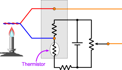
Software compensation This method will calculate the temperature of the junction, by monitoring the temperature inside the isothermal block. For this reason, a thermistor is placed there where the copper connection is made. The signal from the thermistor is transmitted then directly to the PLC (or computer or controller) which it will convert it into the voltage that the junction would create in this temperature (see the 3rd law of thermocouples). This voltage will be added to the measured voltage of the thermocouple, and through the voltage to temperature table, the temperature is calculated. This is a very simple way of connecting thermocouples to controllers and will require only 1 thermistor for all the thermocouple connections inside the same isothermal block. Yet, the compute time, especially if a PLC is used, is usually slow. If a thermistor is used for compensation anyway, why do we use the thermocouple? This is gonna be a short paragraph with a long title. Thermistors are used in a narrow temperature range, usually bellow 200oC. Thermocouples can be used to measure temperatures as high as 1800oC (3272 F), and as low as -270oC (-454 F). Converting from voltage to temperature - The EMF vs Temperature table The thermocouple pairs are usually chosen in a way that they have stability, repeatability and -if possible- linear results. As the K-type is the most popular, we will work on this. First of all, you need to provide yourself the EMF vs. Temperature table for thermocouple. Each type has a different table of course. In this page you will find a complete list with these tables. To follow this article, download the Thermocouple Type K(° C). Now, how to read these tables. I will get a small part (from 0oC to 90oC) to explain. Here is the example: 
So, here how it goes. In the very left column there are the temperatures. Can be at oC of oF. The second column (witch i have masked with red color) shows the actual voltage that will be generated by the thermocouple. It can be in mVolts or uVolts! This table shows the voltage in mili-volts. For example, 3.27 mVolts corresponds to 80oC. All the other columns, are the intermediate temperatures (1 degree step) of the temperatures. For example, at 10oC the voltage will be 0.4mV, but at 16oC the voltage will be 0.64mV! At 69oC the voltage will be 2.81mV and so on. It is actually straight-forward to get the temperature from the voltage. And what can do with this table after all??? There are actually temperature controllers that can do all the hard job for you, and furthermore can be programmed to do several tasks, such as activating relays in specific temperatures of ranges. The thermocouple is directly connected on them, and they usually do the junction temperature compensation internally. Using such a controller, the above table is just... useless. But, what if you want to make a temperature controller by yourself? Most possible you will use a microcontroller for this, and an analog to digital converter. By converting the voltage into a digital value, you can use this table to get the temperature. From voltage to temperature - Solving a polynomial There is a possibility that a processor may use the above table to compare the measured voltage and calculate the temperature. There is also a mathematical way to solve this problem. The temperature can be calculated by solving a polynomial, and as usually, they are long. Here us the sum: 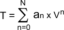
an for a K-type thermocouple can be found from the following table:
If this looks Greek to you, i will show you an example. Suppose that the measured voltage (forget about the cold junction compensation) is 3.7 mVolts. First, we convert to volts, that is 0.0037 volts. Now to solve the polynomial: T = a0 x V0 + a1 x V1 + a2 x V2 + a3 x V3 + a4 x V4 + a5 x V5 + a6 x V6 + a7 x V7 + a8 x V8 I do not find any particular reason to further solve the above anaconda, as requires only plain mathematics. The result is: T = 89.68oC. If you look at the table above, you will see that it is a good approximation to the real temperature provided by the table. Common thermocouple problems We referred to this extensively in this article. Connecting a thermocouple to copper (or other metal) will create another thermocouple. We need to compensate the temperature on this junction. Wire resistance:To keep a good accuracy and response time, thermocouple wires are usually kept thin. Yet, thin wires means high resistance. Most temperature controllers are programmed to compensate this resistance. There are cases that thermocouples needs to be placed many meters away from the controller. In such case, the wire resistance needs to be taken into account. To solve this problem, we use a technique called "compensated ohms measurement". The controller first measures the offset voltage without the ohms source resistance. Then the ohms source resistance is switched on and the voltage across the resistance is measured again. The voltmeter compensates with software the offset voltage of the thermocouple and calculates the real thermocouple source resistance. Decalibration:This is the most annoying error, as the temperature reading appears to be valid, although it is wrong. This error occurs when the makeup of thermocouple wire is altered. This is usually caused by the diffusion of atmospheric particles into the metal when operating in extreme temperatures, or in chemicals. Noise:This is common to all electronic applications when operating into electrically noisy environments. Yet, thermocouples can suffer much greater influence from external noise, as the output voltage from a junction is measured in micro-volts. There are of course methods to minimize noise problems. First of all, an analogue filter at the input of the voltmeter will reduce dramatically external noise. Due to the fact that thermocouples will generate only DC voltage and external noise comes from AC or pulsed voltage, the use of capacitors will reduce such noises. Yet, the acquisition time will be reduced. Another simple method is the use of twisted pair wires, same as used in ethernet cables. To further reduce external noise we can use shielded grounded wire.Finally, a very attractive method to virtually eliminate noise is the integrated A/D convention. The thermocouple is connected into a transmitter (that can compensate the connection temperature as well). The transmitter will convert to digital and also average the signal so to reduce the noise. Then, it will transmit a clear signal onto far distances. This is by far the best way to eliminate noise when measuring in far distance. Thermal ShuntingThermocouples have some mass. To read the temperature, the thermocouple mass must be heated. To heat this mass, an amount of energy will be needed. If the heating source does not constantly provide energy (like a boiler does), then the thermocouple will "draw" an amount of energy from the source and thus the reading will not be accurate. On the other hand, The wires of the thermocouple itself and the housing will dissipate another amount of energy in the atmosphere. To average this problem, there are thermocouples with different wire thickness and different housings. Using the proper type will allow a better reading. For example, a thin wire with small housing is popper for measuring lower temperatures, with faster response time. Common Mode VoltageThis problem refers to parasitic voltages. They can occur for example by inductive pickup near the voltmeter. Most often, such problems occur from bad insulation in connections or the thermocouple itself. If for example you are measuring the temperature of water in a water tank and the thermocouple is badly or no insulated, then possible some volts will exist between the tank (or metallic pipes) and the earth of the voltmeter. To avoid this problem, properly insulated thermocouples should be used, and precautions such as for noise should be taken. Things to remember about thermocouples Two dissimilar metals of any kind, can perform a thermocouple. There are certain metal pairs that have quite a linear behavior in temperature change and good temperature gradients. The thermocouple will NOT measure the temperature of the hot junction. It will measure the temperature difference between the hot and the cold junction. If for example the hot junction is measuring boiling water and the thermocouple to copper junction is at 25 degrees, the measured temperature will be 75 degrees (100-25) Thermocouple needs the cold junction compensation because of the reason previously described. A temperature measurement (with thermistor or diode or embedded chip) is required there where the thermocouple wires are connected with the copper wires or the measuring instrument, for the cold junction compensation. Thermocouples suffers from external noise due to the small magnitude of the Seebeck voltage. In harsh environments with electrical noise, appropriate filters must be applied, along with shielded wires. The thicker the thermocouple junction, the higher temperatures it can measure, but the slower response it has. If measuring in conductive environments like water, the thermocouple probe must be isolated. If the cables of the thermocouple wires must be extended to reach the controller, then choose thermocouple extension wires of the same type as best solution. Thermocouple wires can be also extended with copper wires. If the temperature across the whole length of the copper wires is the same, then the cold junction compensation can be performed on the controller. Otherwise, the compensation must be performed according to the temperature where the copper wires are connected to the thermocouple wires. Comments
|
|
 Contact Contact
 Forum
Projects
Experiments
Circuits
Theory
BLOG
PIC Tutorials
Time for Science Forum
Projects
Experiments
Circuits
Theory
BLOG
PIC Tutorials
Time for Science
 RSS RSS
Site design: Giorgos Lazaridis © Copyright 2008 Please read the Terms of services and the Privacy policy |


 Reddit this

