I was fascinated with the look and feel of the touch button when i first turned on my brand new TFT monitor
Mechanical buttons and switches cannot become obsolete for various reasons. First of all because of the unmatched reliability, and also for the tactile feeling, which stimulates the finger's touch feeling. But they can never be as elegant and flexible as a touch button. There are many different technologies to make a touch button, others applied on surfaces, others on LCD displays, others behind glasses, others on metallic surfaces etc etc etc. The most common ways are the resistance, the capacitive and the inductive touch buttons. In this theory page, i will explain in details the following types of touch switches (which are actually the most popular and easy to make):
The Resistance touch switch
The AC hum touch switches
The Capacitive touch switch
The Resistance touch switch
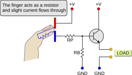
The resistance touch switch is based on the fact that human tissues (like the skin), have a great amount of water and salt, something that makes it conductive. Look at the following drawing:
This is the most basic type of touch switch, in its simplest form. The operation is simple. A transistor is used as a switch. The RB resistor keeps the base to ground when no electrode is touched, so it does not float. The RP resistor is for protection, in case that the electrodes are short-circuited, and it prevents an over current that will probably toast the transistor. If one of the electrodes is touched, nothing will happen. But if both electrodes are touched together, then a small amount of current will flow through the skin to the base of the transistor. The transistor will then go from cut-off to saturation, and current will flow from the CE region to the LOAD.
There are numerous different ways to implement a resistance touch switch, with transistors, with 555, with 741, with CMOS and many more. The idea is always the same though: Two electrodes are used for the touch plates. Current flow from the human skin from one electrode to the other, which finally stimulates an amplifier or another current sensitive part. This method is straight forward and no more info is needed.
Advantages: Super simple, super reliable
Disadvantages: Not very flexible in design, two electrodes required
The AC hum touch switches
My body induces 800 mVolts 50Hz. I'm a living generator! Morpheus would agree, right Neo?
I was not sure if i should mention this type of touch switch. I finally decided to include them, because it seems than many people tend to confuse the AC Hum touch sensors with the capacitance touch sensors. The AC hum sensors are based on the fact that -again- the human tissues and skin are conductive, and also that AC lines produce a magnetic field. Any conductive material placed inside this magnetic field, will produce a slight potential between the item itself and the earth. The same happens of course with the human body.
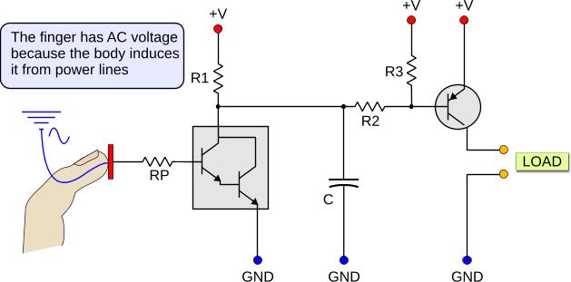
An AC Hum touch sensor uses a high gain amplifier such as a darlington pair to amplify this parasitic voltage. When 50 Hz (or 60 for some countries) are detected, it will arm the load. Here is a basic circuit with such a sensor:
The amplified (and inverted) AC signal that comes from the darlington pair is smoothed on the capacitor C. This capacitor acts as a basic frequency to voltage converter. The PNP transistor acts as a switch for the load. If a slight voltage is applied to the sensor plate (upon finger touch for example), the overall voltage across the capacitor will be reduced, because it is not powered any more with DC current, but from the amplified 50 (or 60) Hz AC current. The PNP transistor will then sense this change and the CE contact will become conductive, providing current to the LOAD.
This design has a few problems. First of all, in order to operate, there must be power lines near by. And i do not mean right above the body, but in the near. In a room for example there are plenty of power lines. But if no light is turned on and no appliance is operating, then no current flows within these power lines, thus no field is generated. So, if you plan to make a light switch with this, then keep in mind that most probably, the light has to be already turned on for the switch to operate (!!!).
And something else... What do you think that will happen, if you walk bare-foot on the cement? Right! A huge amount of the voltage will be grounded to earth through your feet. It is most likely, that the remaining potential will not be able to trigger the base of the darlington transistor, unless you have some serious amplifier over there.
Result: This is a nice educative circuit to study and learn, but in most cases completely improper to use as a switch. Maybe could fit to other applications.
Advantages: Simple circuit, with one single sensor electrode only
Disadvantages: Unreliable in operation - Require power line near by
@Marc Hello. The 555 solution was not very reliable so i have not post the circuit. It seems though that many people keep asking me for this circuit and i may consider to analyze it one day. Maybe.
And, i'm currently writing the BJT transistor theory. When i finish with this, the next step is the PIC theory... Stay tuned
At 13 December 2013, 12:54:31 user Marc wrote: [reply @ Marc]
Hi,
Very great viedos! Congrats!
I would like to know is you can get us the full schematic layout on the device when using the LN555.
I have a question, what is the power consumption when in hidle?
I also like a lot the architecture using the 2 ADC, but I don't have an experience programing PICs. =/
@reuben Test with separated batteries (not PSU). Maybe it comes from the supply.
At 27 February 2013, 8:07:58 user reuben wrote: [reply @ reuben]
i have encapsulated condenser capsule head in steel basket,and pcb electronics in steel tube,both hardwired to ground...and there was still no reduction in hum. the amplifier is JFET source follower class A,can a class A amplifier hum
@reuben maran First, use shielded wires and make a shielded box. Then, make sure that you are not close to an EMI source like your PC for the tests. My guitar hums if i approach my PC
capacitance question
hello sir,thankyou for your capacitance switch videos. i have a diy condenser microphone with class A JFET amplifier [only one transistor] powered by 48V phantom power from a Behringer Xenyx 802 mixer.
it hums loudly [0dbV] ,but when i grip the ground the hum reduces. i removed the source resistor off the JFET ,so that the amp was dead, and the hum was gone. so i knew it was not produced by the rest of the circuit.
i feel this hum could be produced by capacitance. the circuit in your capacitance switch video,how does one remove the capacitance?i appreciate very much any reply. i have a schematic but not an email address but mine is reuben.maran@gmail.com.
thanks,reuben.
I WILL TRY THIS THEN REPLY U. BUT I REQUIRE HEX CODE FOR PIC MICROCONTROLLER FOR ALL 16 INPUTS. ALSO PL EXPLAIN HOW MAKE 64 INPUTS THROUGH 74HCT573. & HEX CODE PLEASE TO MY MAIL ID: hrd_comfort@yahoo.co.in;
@david Bad news - There must be no galvanic contact between your finger and the foil. Use a thin (3mm) plastic above the sheet - It has to work even with the plastic
At 14 February 2013, 8:12:59 user david wrote: [reply @ david]
hey,
I was building a circuit with the capacitive sensing. I build a touch pad by connecting a wire out of a circuit to a aluminum foil. And the sensor works by directly touch the aluminum foil using your finger.
But then the TA told me direct touch is not really a capacitive sensor, because there's no distance between the two plates. But the circuit works. But according to you, number two method is the direct touch, and the finger is actually a capacitor itself.
@Pedro Sousa for the resistors, you need to make some tests yourself to find the proper values. You can start with RP=220 and RB=22K, which is a good selection.
As for the CMOS solution, you can select for example a quad AND gate (4081). Keep one input H and the other input like the transistor input. Bur i would still stick with the transistor method with SMD transistors
Hi Giorgos,
I'd like to do a panel with 50 Resistance Touch Switches for 5 V DC.
In your video clip you are using a 2N2222 transistor and in the text you say I can instead use a CMOS or other devices.
I'm looking for reliable and cheap switches.
My questions:
1. With 2N2222, what will be the values for RB and RP.
2. If I use a CMOS:
- The circuit is exactly the same?
- Which CMOS should I purchase?
- What will be the values for RB and RP?
- Is it more expensive?
3. For so many buttons, should I use other solution?
Best regards
Pedro
@saravanaeswaran first, you do not need to spam a message in all boards asking the same thing, it is not helpful for other users. You can find similar circuits with capacitance sensors in the "circuits" section of the site:
http://www.pcbheaven.com/circuitpages/
All circuits have complete documentation, schematics and PIC code. If you ask for another variation of a circuit we do not make circuits on demand.
Hi there,
I want to start making a project so I can control a relay with this switch:AC hum touch switches.Can you send me an email with the names of the parts so I can bulid it?Thanks
Hi andrew, this page is only the theory. Go to this page
http://pcbheaven.com/circuitpages/
I have 3-4 circuits with detailed diagrams and explanations.
At 15 February 2011, 5:12:51 user andrew wrote: [reply @ andrew]
thanks for the diagram of the resistance touch switch. I guessed kind of close to the right way but this clears it up. It took me forever to find a diagram! Now if only the resistor values were there...
Manish, i will post a dedicated page for each circuit in the near future. i already began with the resistance touch. follow RSS or twitter to be notified.
At 16 January 2011, 13:15:01 user Manish wrote: [reply @ Manish]
I like the capacitance touch circuit. Can this circuit work in bistable mode using relay for on/Off the appliances. If possible please mail me the part list & schemetic for the same. Thanking u..............

 Home
Home
 Projects
 Experiments
 Circuits
 Theory
 BLOG
BLOG
 PIC Tutorials
 Time for Science


 Contact
 Forum
Forum
 RSS
RSS


 Reddit this

