Home     Contact     Projects     Experiments     Circuits     Theory     BLOG     PIC Tutorials     Time for Science     RSS     Terms of services     Privacy policy  
   
 Home      Projects     Experiments     Circuits     Theory     BLOG     PIC Tutorials     Time for Science   

25 March 2009
Author: Giorgos Lazaridis
The SCR

History

Those devices as well as the thyristors, are based on the work of Bell laboratories. The leader of the research was John Moll. His goal was to make a replacement of the solid state relay with no moving or any other mechanical parts, that was finally achieved during 1954.

The first series of SCRs where designed, created and characterized just two years later, and by then they had only two leads. That year the SCR took it's final outlook with 3 leads.

Silicon Control Rectifiers was finally commercializes by General Electric. The champion of SCRs is said to be Bill Gutzwiller. He start working by General Electric in January 1955 in an engineering role at the rectifier manufacturing site at Clyde where Ray York was site director.

Due to the prior work of Bell laboratories, General Electric did not patent the SCRs as there was no invention or record as far as the legal matters are concerned.


SCR Symbols and equivalents

The electronic circuit symbols of the Silicon Controlled Rectifier are as follows:


The equivalent of a Silicon Controlled Rectifier is actually a set of two transistors, one NPN and one PNP connected back to back:


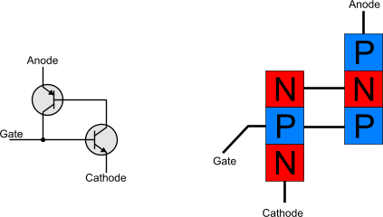
This transistor set will perform the Silicon Controlled Rectifier that is actually a PNPN contact as follows:


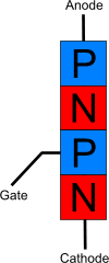
How SCR work

The SCR's basic function is to replace the relay switches with a non-mechanical part. Modern SCRs are capable to handle loads with voltage ratings of up to 7500 volts, and with current ratings up to 3000 amperes RMS amperes per device. Special SRCs could manage loads even over 50 kA in single-pulse operation.

Due to the lack of mechanical moving parts, an SCR has a much longer lifetime than a relay. Moreover, it can turn on and off a load in speeds that could reach the 25.000 times per second, when a small relay could cycle no faster than 100 time per minute.


The PNPN layers of an SCR

An SCR could be considered as a pair of two transistors connected back to back

An SCR is made up with four layers of semiconductor material arranged in the order P-N-P-N. Consider an SCR as a transistor pair, one NPN and one PNP, connected back to back. The Anode 'A' is attached to the upper P-layer and the Cathode 'C' is connected to the lower N-layer. There is another lead called Gate 'G', that is connected to the mid P-layer.

During the operation of an SRC, the collector of Q2 drives the base of Q1, while the collector of Q1 feeds back to the base of Q2. The gain of this positive feedback is the product of the Beta gain of the first transistor multiplied by the Beta gain of the second transistor. When this product is less than one, the circuit is considered to be stable, otherwise the circuit is regenerative. A smll negative current applied to the Gate, will bias the NPN transistor into cutoff and will drop the gain of the feedback under 1. By that time, only a slight current can exist between the Anode and the Cathide from the very small cutoff collector current of the transistors. Therefore, the impedance between the anode and cathode is very high.

When a positive current is applied to the Gate lead, the NPN transistor is sent into a conductive state causing the collector current to rise. The gain of the feedback will increase by the increment of the gain of the NPN transistor and will become regenerative. The collector current on both transistors will be increased to a value limited only by the external circuitry. Both transistors are driven into saturation and the impedance between Anode and Cathode becomes very low. If the Anode-Cathode is forward biased, the current will flow within the SCR and will only find a very slight resistance. If this happens, then the positive current on the Gate is no longer needed in order to keep the Anode-Cathode conductive, as the transistors will perform a self-regenerative action. The SCR will remain in this condition as long as the Anode-Cathode voltage becomes zero or reverse biased.

The following curve is the characteristic curve of an SCR with no current or negative current on the Gate. If the Anode-Cathode voltage difference is greater than the Breakover Voltage, the SCR goes into a state that this contact becomes highly conductive, the current increases rapidly and reaches greater values than an SCR can usually handle (due to the high voltage already applied) and thus, the SCR is destroyed.

The same effect is occurred when the voltage difference between the Anode and the Cathode becomes reverse and higher than the Reverse Breakover Voltage.


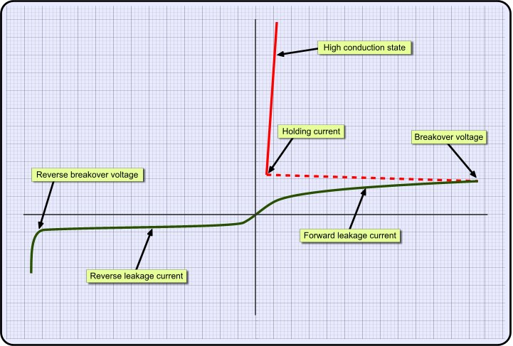
The next image shows the characteristic curve of an SCR the time that some positive current flows from within the Gate lead. The breakdown voltage is significantly reduced with the effect of a very slight current applied on the Gate. If by the same time voltage is applied between Anode and Cathode, current will flow from within this contact. Due to the fact that not very high voltage is needed any more, the current is controllable from the rest of the circuit and therefore it will not increase into values that may destroy the SRC. The SRC will remain conductive as far as the Anode-Cathode contact is held forward biased (positive voltage applied to Anode and negative to Cathode), with no respect to the Gate current. This means that even if there is no voltage applied to the Gate, the SCR will remain conductive.

Still, if the SCR's Anode-Cathode is reverse biased and the voltage is higher than the reverse breakover voltage, the SCR will be destroyed.


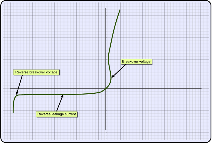
SCR gate triggering

A very simple triggering circuit can be seen below:


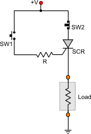
The circuit has two push buttons. SW1 is a normal open (NO) pushbutton, while SW2 is a normal close (NC) pushbutton. If SW1 1 is pushed, a current will flow within the protective resistor R right in the Gate of the SRC. That is enough to trigger the SRC.

To calculate the protective resistance, you have to know the gate voltage VG and the gate current IG needed so that the gate pulse will turn the SRC conductive. If you know that, then you can apply to the following formula:


R = (V - VG) / IG

If for example a thyristor has VG = 3V and IG=150mA and the supply voltage of the circuit is 12V,


R = ( 12 - 3 ) / 0.15 => R = 60 Ohms.

As long as the SW2 is concerned, it's purpose on the circuit is to turn the SCR into no-conductive state. When SW2 is pushed, the Anode will have no more positive voltage and therefore the SRC will act as a circuit break.

The above circuit is a very simple version of a triggering circuit. It could be much more complicated according to the needs of the application. The most commons applications for an SCR is the power delivery control. Inverters, dimmers, switching power supplies and many more power-delivery and control equipment uses the SCR as the final stage to deliver controllable low or high power.


Relative pages
  • The TRIAC theory
  • Learn how dimmers work
  • PWM signal theory
  • Basic transistor circuits
  • How to make a light / dark activated switch - 3 different circuits under the microscope
  • Dr.Calculus: Standard resistor values calculator


  • Comments

      Name

      Email (shall not be published)

      Website

    Notify me of new posts via email


    Write your comments below:
    BEFORE you post a comment:You are welcome to comment for corrections and suggestions on this page. But if you have questions please use the forum instead to post it. Thank you.


  • At 1 June 2014, 13:24:26 user SALAM wrote:   [reply @ SALAM]
    • thamks


  • At 4 June 2012, 17:36:05 user Giorgos Lazaridis wrote:   [reply @ Giorgos Lazaridis]
    • @awuu So you suggest that everyone who writes theory regarding the SCRs (or something else) should write different things? It's not a theatrical play, it is standard theory... From wherever you read the theory of a part (like SCR ), you will eventually write something similar to someone else. By the way, i wrote the theory from a book from high school...


  • At 4 June 2012, 14:53:14 user awuu wrote:   [reply @ awuu]
    • COPY and PASTE from NEETS MODULE NO. 7


  • At 7 December 2011, 21:11:22 user Kammenos wrote:   [reply @ Kammenos]
    • @Sanjay adhikari i'm sorry but i have not test it. I'm sure it is not going to be easy. You need to put resistors to protect the base current.


  • At 5 December 2011, 1:01:34 user Sanjay adhikari wrote:   [reply @ Sanjay adhikari]
    • Sir, i used BC547(npn) and BC557 (pnp) to make SCR but it is not working.what changes are necessary to make it working?


  • At 30 October 2011, 6:12:38 user Kammenos wrote:   [reply @ Kammenos]
    • @RaymondB Once the gate of the SCR is triggered, the SCR stays in conductive state as long as:
      1. The gate has voltage OR
      2. The Anode-Cathode are forward biased.


  • At 29 October 2011, 19:00:06 user RaymondB wrote:   [reply @ RaymondB]
    • So then let me see if I understand this, an SCR works much in the same way as would a self locking ice cube relay on with the SCR there is no need for the negative of the circuit to keep it energized. The SCR will stay conductive as long as the load is present ? Is that correct ? or am I still missing something.


  • At 29 October 2011, 6:46:29 user Peter O wrote:   [reply @ Peter O]
    • I find the theory of SCRs a bit daunting.
      Suspect I am not the only one here.
      So why not show in the explanation just how an electro-mechanical relay could be replaced by an SCR, or SCR pair.
      If your readers can't figure that out, then your explanation has gone wide of the mark & I regret I can't I can't figure this out hence this request.
      THanks


  • At 3 September 2011, 18:13:42 user Kammenos wrote:   [reply @ Kammenos]
    • @Hirak Ghosh for that's the way it works. I do not have enough knowledge to tell you exactly what happens with the electrons and the holes


  • At 2 September 2011, 8:29:56 user Hirak Ghosh wrote:   [reply @ Hirak Ghosh]
    • In Triac characteristics expt , Why gate current increases when Triac in high conducting state ?

      Hirak


  • At 7 April 2011, 15:47:06 user Kammenos wrote:   [reply @ Kammenos]
    • @Fung if a diode (like an LED) has the same resistance in both directions, you can be sure it is destroyed. But a destroyed LED may also have a circuit break, and have infinite resistance in both directions. Also, keep in mind that the semiconductor you describe (the one with infinite resistance) does not exist. All have a huge resistance allowing some current to flow, but this is not significant. You can find this value in the datasheet of each part, named "Leaking or leakage current". So, a semiconductor that has increased leaking current may also be considered as destroyed, same a semiconductor that has increased forward resistance (like in your case).
      The point is that, this changed characteristic shows that your part has changed its composition (of electrons and holes) in a PN junction. You can't rely on this anymore, unless you want to work with it for researching reasons, or out of curiosity.


  • At 7 April 2011, 14:35:08 user Fung wrote:   [reply @ Fung]
    • So, after the resistance of the gate had increased to 170kohms, how much current is required now to trigger the gate again? I think that it should be much greater than before it burns.

      It is known that typical triggering current of the gate of BT169G is 50uA (which the gate resistance is 820ohm) when Vdd=12V and I=10mA, how about the damaged SCR at now?

      ----
      As I know that, semiconductor-made parts have the property that is allow current flow in exactly one direction, if the part is connected in reverse, it has an infinite resistance. If a semiconductor is "destroyed" and it has resistance even it is tested in reverse (which is impossible if the chip is in good condition), can I say that it is completely destroyed?

      For example, after an LED is burnt due to excess current flowing through it, it is checked that both forward connection and reversed connection testing have the same or similar resistance, such as:

      In good condition (just an example):
      [+]=>[-], 1040ohms
      [-]=>[+], infinity

      The destroyed:
      [+]=>[-], 1105ohms
      [-]=>[+], 1106ohms

      It can be concluded that the LED is completely destroyed, am I right?


  • At 6 April 2011, 20:22:49 user Kammenos wrote:   [reply @ Kammenos]
    • @Fung sometimes electronic components are not totally destroyed, but they alter their characteristics. I remember once i had a PIC, and i was trying to make a low current application. I was expecting some 1mA during operation and less than 20 micro amperes during sleep. Yet, i had all the time 20 mAmperes. After a short discussion with microchip engineers, they told me that some times, due to over current or static electricity, the composition of the P and N materials is changed. This does not always mean that the part is destroyed, but the lifespan of this part is dramatically decreased and it will be totally destroyed shortly...


  • At 5 April 2011, 5:54:15 user Fung wrote:   [reply @ Fung]
    • I have a SCR "BT169G" which is destroyed accidently from short circuiting on the gate and it is replaced by a new one.

      Refering to the normal SCRs, the resistance from gate to cathode is about 820ohms and infinity when reversed. For this destroyed SCR, it is found that the resistance from gate to cathode has gone up to 170kohms, but remains infinity if reversed, so I think that it is not totally destroyed).

      Is it cannot be used anyway?

      PS: Given that the power supply of the related circuit is 5.2V, a button and a 10kohms resistor is connected in series from the supply to the gate of this SCR.


  • At 4 August 2010, 14:29:05 user ERic wrote:   [reply @ ERic]
    • What if the condition below?
      Given Vg=1+ 10Ig. The gate source voltage is a rectangular pulse of 15V with 20micro second duration. For an average power dissipation of 0.3W and peak gate drive power of 5W. Determine

      i) Resistance to be connected series with the SCR gate.

      ii)Triggering frequency

      iii) The duty circle.


    delicious
    digg
    reddit this Reddit this
    Faves


     HOT in heaven!


    NEW in heaven!


    New Theory: AC electric motor working principle


     Contact     Forum     Projects     Experiments     Circuits     Theory     BLOG     PIC Tutorials     Time for Science     RSS   

    Site design: Giorgos Lazaridis
    © Copyright 2008
    Please read the Terms of services and the Privacy policy