The discovery began in the middle of 1821, where J. T. Seebeck discovered that two not similar metals, if they are connected in 2 different points and those points are held in different temperatures, there will be a micro-voltage developed. This effect is called the "Seebeck effect" as of it's discoverer.
Some years later, a scientist discovered the opposite of the Seebeck effect. He discovered that if someone applies voltage to a thermo-couple, one junction shall be heated and the other shall be cooled. The scientist was called Peltier and the effect called the "Peltier effect".
What is the Peltier thermo-element?
A Peltier thermo-element compared to a AA battery
A Peltier thermo-element is a device that utilizes the peltier effect to implement a heat pump. A Peltier has two plates, the cold and the hot plate. Between those plates there are several thermo couples. All those thermo couples are connected together and two wires comes out. If voltage is applied to those wires, the cold plate will be cold and the hot plate... hot.
The device is called a heat pump because it does not generate heat nor cold, it just transfers heat from one plate to another, and thus the other plate is cooled. It is also called a thermo-electric cooler or TEC for short.
Because TECs have several thermocouples, a lot of heat is transfered between the plates. Sometimes it can reach a temperature difference of 80 degrees Celsius or more!
What are Peltier elements made of?
Peltier thermo-elements are mainly made of semiconductive material. This means that they have P-N contacts within. Actually, they have a lot of P-N contacts connected in series. They are also heavily doped, meaning that they have special additives that will increase the excess or lack of electrons.
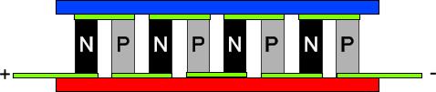
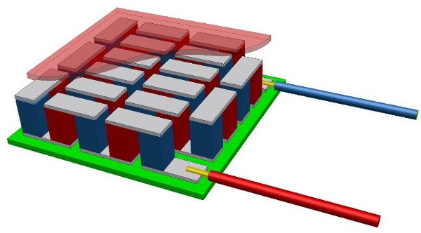
The following drawing shows how the P-N contacts are connected internally within a Peltier TEC:
Now, imagine tens or hundreds of those P-N material between two plates. The following drawing shows how can many P-N contacts exist in a rectangular area like a Peltier TEC.
You can see how the P and N material are connected in series together to implement a long strip of P-N junctions. The top plate is the hot plate and the bottom is the cold plate. When power is applied to the two wires, the heat will be transfered from the cold plate to the hot plate and thus the cold plate shall cold.
Peltier Markings
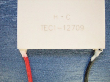
Sometimes, the TECs have identification markings on their face, just like the following picture:
In this picture you see the ID: TEC1-12709
The first two digits shall be always "TE"
The next digit shall be "C" or "S". "C" stands for standard size and "S" for small sized.
The following digit is a number and indicates the number of stages that the TEC has. In our example (and the vast majority of TECs) is a one-stage TEC
Right next comes a dash. After the dash, the 3 first digits indicates the number of couples that the TEC has inside. In our case it has 127 couples. If the couples are 2-digit, then the number has a leading zero, for example 062 for 62 couples.
Next comes two more numbers that indicate the rating current of operation for the Peltier. In our case this is 9 Amperes
Some times follows a "T" and three numbers. This indicates the maximum operating temperature for the TEC. For example, "T125" is 125°C rated.
Peltier characteristic curves and operation
Peltier elements can give more than to 80°C temperature difference between their plates. But this is not a standard value. Actually, this would only be achieved in ideal conditions. The actual temperature difference (ΔT) is usually smaller. The specifications of a TEC usually shows the achieved temperature difference in conjunction to the power transfered in watts. The diagram should look like the following:
Looking the above diagram, we can calculate the temperature difference that will be achieved according to the power that the TEC will have to move across the plates. The power is measured in watts, but we actually talk about the thermal power. You can use our temperature unit converter to convert watts to your desired units.
You should not confuse the power of Peltier operation with the power that it transfers. It is most common that TECs are sold with the electric power indicated. A 125 Watt peltier may NOT be able to transfer 125 Watts of thermal power across the plates. Instead, it is most possible that it will draw 125 Watts electric power at max conditions.
Peltiers comes usually with the datasheet that indicates the performance curves of the device. Those curves are essential if you want to make your theoretical calculations for the optimal device operation.
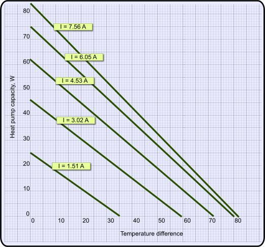
The first characteristic curve for a peltier is the Temperature difference vs Heat pump capacity. This curve indicates the temperature difference to be achieved in order to pump specific power of heat. It may be one or more curves for different current loads. An example of such a curve is shown in the following diagram:
The above curves comes from a real Peltier and are not imaginary. What we could conclude from the above is that if we need for example to transfer 30 Watts of heat, then - with appropriate voltage as we will see right next - there would be created a temperature difference of 20 degrees and the TEC would draw as much as 3.02 Amperes.
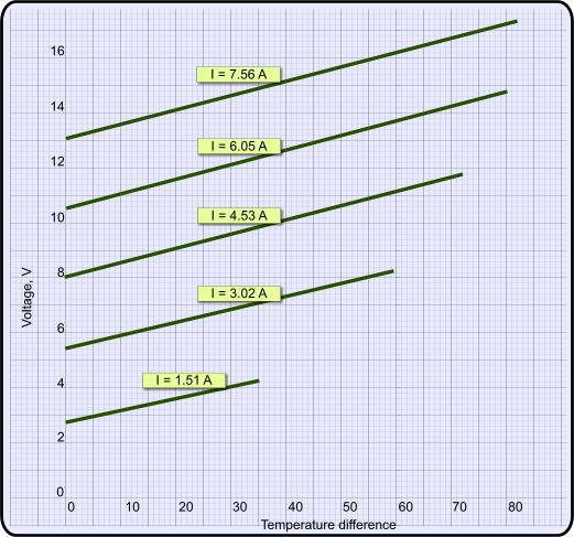
The next characteristic curve is the Temperature difference VS voltage. With this curve, we can calculate the voltage needed to be applied on the TEC in order to achieve the appropriate temperature difference. Here is one -also real- characteristic curve:
Let's continue the example we started before. We calculated that we need 20 degrees temperature difference and 3.02 amperes to achieve the 30 Watts power transfer. How much voltage must we apply to the Peltier to achieve this? From the above diagram, it's easy to find that we need about 6.5 Volts.
At 26 August 2015, 3:53:21 user pev69 wrote: [reply @ pev69]
The explanation is somewhat misleading. The P- and N-type semiconductor pellets do not work as pairs or junctions, but work individually. The whole TEC could be made of only P or only N pellets, but because the electrical connections between pellets would then need to zig-zag between the cold and hot sides, they would reduce efficiency by conducting heat back to the cold side. So the only reason to use both P and N (and alternatingly) is to have the electrical connections between adjacent pellets stay on one (cold or hot) side.
Hello sir/madam
Informations are very much useful, but how to calculate the heat transfer in watts depends on the application.. Could tell me how to make a small thermo electric cooler
Kindly reply me @ mahesh.chandran@lnttechservices.com
Dear Sirs,
I would be interested to know the effciency of a Peltier module when temperature has reached the set point and switches off. Since the module is a heat transfer unit and we have two heat sinks with a high temperature diference surely the cold side will transfer the heat to the cold side. If that could be the case, I would imagine a great loss of heat.
Many thanks,
Chris
@Giorgos Lazaridis
soory i was wrong, didn t pay attention to the description (i watched it late at night), the copper was used as heat sink a peltier chip is hidden between two stainless steel plates
@Giorgos Lazaridis you can make thermocouples out of iron and copper,
to make the most efficient possible peltier you would need doped metals but for a "fonctionnal if observed with a voltmeter" iron and copper should do it, i found a vid on youtube of a guys actionning a small motor with a weird peltier made of inox and copper tubes
@ngc1300 as far as i know, simple metals won't work. Peltiers have semiconducting materials, not same as transistors or diodes. They have lots of additives to allow many free electrons to form. It won't be that easy like getting two metals and connecting them. You can start by adding additives to pure silica.
@Giorgos Lazaridis
i'd like to try at least, i'm kind of hyperactive and i love doing physics experiments and building stuff (this would be two birds one shot) and I actually would need to build one for a presentation that counts in my exams, i dont need it to be efficient, just to be able to show that it works, but the more efficient the better
if i need pure metals i can buy them there http://elementsales.com/pl_element.htm#f
i can use my schools workshop if required
the peltier design seem pretty straight forward if i knew what materials to use it could be simple,
i might go for iron and copper for the P and N materials, but i do not know what to link them with, if it matters or not
@ngc1300 you want to make a peltier???? this is the first time i hear this. i cannot help you, my knowledge is poor. But if you manage to make one, please let me know. send me an email if you do.
hi
could you please tell me what kind of preferably easily accessed cheap metals I could use to build one?
what to use as N as P and the plates between
I tried to find some but didn't succeed... every single tutorial to build a pelted module sais "buy a Pelletier module" then how to use it as a thermoelectric generator
I would need to buil one for a presentation (I m in a grade between high school and ingenniering school in France) and none of my teachers are capable of givin me any useful information (they really suck as teachers...sadly)
At 30 October 2011, 15:58:10 user Prasad wrote: [reply @ Prasad]
Very impressive this TEC module theory? Just wonder if anyone would have used this to pump water from a deep well.
ok.
my question is that if efficiency is so low(eg. <10%) then the rest of the input power is being wasted. So is it true that the wasted energy is in the form of heat(which is probably why they need cooling always)???
also if for instance we are using it to cool a pc down. As mentioned in article we would have to more than double the coolong right. So why put the TEC instead just double the cooling alone? In other words if we use Peltier chip for cooling, it will along with the CPU heating, produce more heat itself which we will have to cool down altogether. so what is the resulting benifit of using it???
please help i am confused.
Thanx
At 18 November 2010, 4:15:09 user Zach wrote: [reply @ Zach]
You should also mention that condensation (or ice) might form on the cold side which can damage semiconductors like a CPU.
Kammenos, thanks.I shall go through the material in more detail. I visited the website www.top-cool.eu. I saw the product with two water circulations around Peltier. I assumed I can send water to be cooled through one circuit and pass water through the other circuit which will pass through hotside of peltier. My knowledge is very preliminary and I shall go through the details. Thanks for the warning.
Hello Gurumurthy,
If i understand correct, you want to cool down water from 80 to 20 deg? With 8 liters per minute flow? I think that the Peltier is not capable to do this. If you use a huge scale peltier or multiple peltiers in series, then the power consumption will be completely inefficient. Peltiers may have efficiency as low as 0.5%, which is usually unacceptable.
The peltier is not a heater or a cooler. It is a heat-pump! Draws energy from one plate and transfers it to the other. In other words, regarding the rice application, the cold rice will not become colder, as the hot rice will prevent the peltier to transfer to it more energy. The peltier would work perfectly and with high efficiency, if it had to draw energy from the hot rice and transfer it to the cold, meaning that the hot rice would become cooler and the cold would become hoter.
I am very impressed with the article. I bought a Peltier chip in the year 1995 for deploying in some crazy application like: In India we take curd rice cold and Sambar rice hot. So I wanted to design a tiffinbox to keep one section cool and the other hot. The design never happened due to other work pressure. I got this article when I am recommending peltier to cool a liquid flow of 8 lpm from 80 deg C to 20 deg C. I am sure my friend will learn a lot.

 Home
Home
 Projects
 Experiments
 Circuits
 Theory
 BLOG
BLOG
 PIC Tutorials
 Time for Science


 Contact
 Forum
Forum
 RSS
RSS


 Reddit this

