PAGE 2 of 5 - Schematics
i decided not to put on the same board the controller and triac
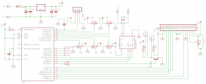
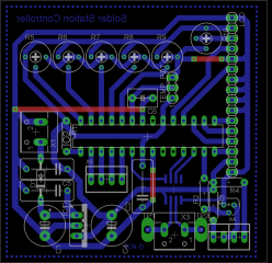
The controller board
 |
 |
on X1 you power the board from 7VDC to 15VDC ( + on pin1 )
on X3 you connect the thermocouple pair ( +on pin1 )
X5 is for feature use
you power the led and optocoupler form X6 and X4 ( the two middle pins are ground )
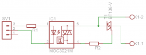
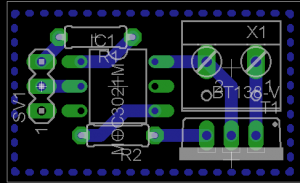
And here is the Triac Board
 |
 |
| | Resistors and Potentiometers - Controller | | R1 | Resistor 470 Ohm 1/4 Watt 5% Carbon Film |  | | R2 | Resistor 470 Ohm 1/4 Watt 5% Carbon Film |  | | R3 | Resistor 1 KOhm 1/4 Watt 5% Carbon Film |  | | R4 | Resistor 1 KOhm 1/4 Watt 5% Carbon Film |  | | R5 | Potentiometer 1 KOhm Linear Rotary 1/2W | | | R6 | Potentiometer 1 KOhm Linear Rotary 1/2W | | | R7 | Potentiometer 1 KOhm Linear Rotary 1/2W | | | R8 | Potentiometer 1 KOhm Linear Rotary 1/2W | | | R9 | Potentiometer 1 KOhm Linear Rotary 1/2W | | | R10 | Potentiometer 1 KOhm Linear Rotary 1/2W | | | | Capacitors - Controller | | C1 | Electrolytic Capacitor 470 uF 25 Volts | | | C4 | Electrolytic Capacitor 220 uF 25 Volts | | | C3 | Ceramic Capacitor 0.1 uF 50 Volts | | | C5 | Ceramic Capacitor 0.1 uF 50 Volts | | | C2 | Ceramic Capacitor 0.1 uF 50 Volts | | | C6 | Ceramic Capacitor 0.1 uF 50 Volts | | | | Diodes - Controller | | D1 | 1N4004 General Purpose Diode Rectifier |  | | | Transistors - Controller | | T1 | 2N3904 NPN General Purpose Amplifie |  | | | IC's - Controller | | IC1 | 7805 Positive Voltage Regulator |  | | IC2 | ATmega8 Microcontroller |  | | IC3 | MAX 6675 Cold-junction compensated K-Thermocouple to digital converter (0░C to +1024░C) |  | | | Other - Controller | | LCD 16x2 Character LCD w/ HD44780U1 controller |  | | | | | Resistors and Potentiometers - Triac | | R1 | Resistor 470 Ohm 1/4 Watt 5% Carbon Film |  | | R2 | Resistor 470 Ohm 1/4 Watt 5% Carbon Film |  | | | Transistors - Triac | | T1 | 2N3904 NPN General Purpose Amplifie |  | | | IC's - Triac | | IC1 | MOC3021 Random Phase Optoisolator TRIAC Driver Output |  |
Comments
At 7 September 2015, 16:51:19 user Berlin_Mitte wrote: [reply @ Berlin_Mitte]Please provide me source code? thank you.
Email: Berlin_Mitte1@yahoo.com
At 11 July 2013, 7:58:45 user Luigi wrote: [reply @ Luigi]Pictures detailed are not available.
Hex file download need explain to describe how are created (IDE AVR STUDIO) to prform corect upload, please.
Thanks.
At 14 March 2013, 17:12:46 user Jay Stillz wrote: [reply @ Jay Stillz]Do you think its possible to convert a pitbull turbo charger, pibull x3 (http://www.competitionelectronics.com/retired-rc-products.html), into a digital slodering station ??
At 23 February 2013, 10:34:29 user Michael wrote: [reply @ Michael]@Hercules Trapierakis Can you please provide us with the source code? thanks!
At 5 September 2012, 20:44:46 user Teo wrote: [reply @ Teo]Hi, good work!
Can you post a C code of this solder station?
Sorry, but i've arduino uno, i have flashed a bottloader into atmel 8, and i want to load the scatch on this chip.
i can't load hex code with arduino, right?
At 7 August 2012, 21:03:18 user Chris wrote: [reply @ Chris]@Hercules Trapierakis
Hi - could you please provide me with the source code?
That knob on the front-panel - is that a potentiometer or rotary encoder?
At 6 August 2012, 2:58:59 user metal wrote: [reply @ metal]Where can I find the source code :(
At 28 July 2012, 14:22:53 user Rohit Soni wrote: [reply @ Rohit Soni]hey hiii... please provide me the source code for this as i m using opamp for thermocouple.... so need to apply some changes to it to work out wid pid... thanks....
bestbuddyrohit@gmail.com
At 11 April 2012, 6:53:57 user Hercules Trapierakis wrote: [reply @ Hercules Trapierakis]@Pantelis
use this one: Controller firmware with P = Kp * Error
the time is selected with R9
At 10 April 2012, 19:15:45 user Pantelis wrote: [reply @ Pantelis]Hello everybody, i made this circuit but i am stacked to the hardest part of the project, i want to programm the avr. I will make this circuit on the breadboard http://electronics-diy.com/avr_programmer.php but i can't understand witch one hex to use,should i place R5-R9, i have understand what PID is ,but i don't know if its a must. If i use these i will have a better accuracy at the pointed temperature i have select?
Who can i determine the time that the solder iron will shut down?
At 24 January 2012, 9:55:08 user herctrap wrote: [reply @ herctrap]@Kammenos
no i haven't
but Yiannis sais that fair easy to make it
At 24 January 2012, 9:46:15 user Kammenos wrote: [reply @ Kammenos]@herctrap have you tried this bungard sur tin?
At 23 January 2012, 23:46:53 user herctrap wrote: [reply @ herctrap]@Kammenos
http://img515.imageshack.us/img515/9435/120123081420.jpg
http://img40.imageshack.us/img40/8284/120123081322.jpg
mine with flx and solder no chemicals
-----------------------------------
search for bungard sur tin
At 23 January 2012, 10:54:16 user Kammenos wrote: [reply @ Kammenos]@herctrap Yes we want a video with the tinning method! ;) ;) I have found some chemicals for chemical tinning, but i can only order large quantities since they are hazard liquids
At 23 January 2012, 6:30:32 user herctrap wrote: [reply @ herctrap]@stij
yes with a lot of flux and solder
but i have learned to do it better
[URL=http://img515.imageshack.us/img515/9435/120123081420.jpg][IMG]http://img515.imageshack.us/img515/9435/120123081420.th.jpg[/IMG][/URL]
[URL=http://img40.imageshack.us/img40/8284/120123081322.jpg][IMG]http://img40.imageshack.us/img40/8284/120123081322.th.jpg[/IMG][/URL]
if you want i will make a video next time
At 22 January 2012, 23:00:59 user Kammenos wrote: [reply @ Kammenos]@stij i suppose with the soldering iron and solder ???
At 22 January 2012, 22:50:27 user stij wrote: [reply @ stij]how do you tin the pcb board and it is silver?
At 18 January 2012, 20:45:17 user herctrap wrote: [reply @ herctrap]user friendly
you can set easily the Kp Ki Kd factors
-------------
i actually used it as a P controller only
i didnt use the pots - i programm it from the software
At 18 January 2012, 17:19:45 user Kammenos wrote: [reply @ Kammenos]one question, why you used potentiometers to set PID values and temp values? Any particular reason?
At 18 January 2012, 17:15:54 user Kammenos wrote: [reply @ Kammenos]Let me say that once more: I envy the "auto turn off" function. If i had time to work with my soldering station, i would add it. |
|
 HOT in heaven! HOT in heaven!

|
|

 Home
Home
 Projects
 Experiments
 Circuits
 Theory
 BLOG
BLOG
 PIC Tutorials
 Time for Science
 Contact
 Forum
Forum
 Projects
 Experiments
 Circuits
 Theory
 BLOG
BLOG
 PIC Tutorials
 Time for Science
 RSS
RSS