Worklog - Let's be scientist for a while (November 6 2010)
I know that the water will get hot. I know that i have to have a means of cooling to avoid overheat. What i don't know, is how powerful this cooler must be. There are 2 ways: The first one is to get some peltiers and run some tests... But i prefer the second one which is more scientific. I can run a test without a cooler and calculate the amount of energy that the water got, and thus calculate the power of the cooler. So, hands on workbench:
First of all, i need a tank with a known amount of water, that is 1 liter, and a thermometer
A small aquarium water pump, submersible
I used these tools to hold the (one) tube steady above the heating lamp
I put the tank in the water and connected the parts with the hose
I made a hydraulic circuit: Tank to pump to tube inlet, to tube outlet, and back to tank
And then i gave power to the lamp, full power. I measured at different times the water temperature in the tank
Here is a table with the experiment measurements (the water was 22oC when i began):
Time (Seconds)
Water temperature (oC)
0
22
180
25
240
26
360
28
420
29
480
30
570
32
690
34
780
35
900
37
1020
39
1200
42
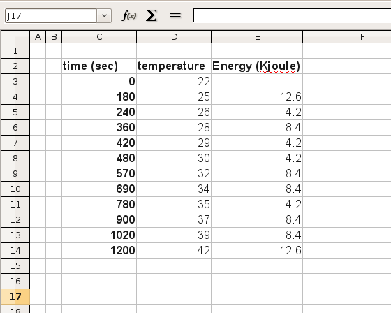
So what with these numbers? What can we do? Well, we know the temperature change over time and the water volume (1 liter), thus the water mass, which is very close to 1Kg (it is not distilled water...). These are enough to calculate the energy that the water absorbed from the lamp over time. To do this, i will use the formula:
Q = m x 4.2 x Dt
Where Q is the energy in KJoules, m the mass of the water in kilos, 4.2 is a constant in KJoule/Kg/oC, and Dt is the temperature difference. In the open-office spreadsheet, i made a table to do all these calculations. Here are the results:
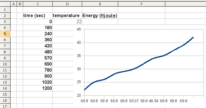
In a first glance, its obvious that the temperature change over time looks linear. A chart should show this more clear. So, i made a smooth-line chart representing the water temperature increment over time:
It should be linear. The changes you see in the graph are obviously due to error measurements. The thermometer is not an expensive sophisticated laboratory thermometer after all... So, i bet the change is linear over time, at least for the range of temperatures that i will work (not above boiling point).
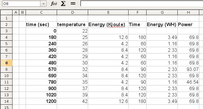
So, now i know that the amount of power provided to the water is always the same. Of course it is! The lamp was full power all the time, the water flow was stable, the water mass was also the same... Nothing changed. But how much power was provided to the water? I know that the lamp is 850 Watt but not even the half of it is directed to the water. To calculate the power, i will use the formula
P = E / t
Where P is the power in Watts, E is the energy in W-hours and t is the time in hours. In the next column of the table, i added the relative "time" in seconds, following i made a column with the conversion from KJoules to Whours (1 WHour is approximately 1KJoule x 0.277). Finally, i divided the values (did not forget to convert W-Hours to W-Seconds) and here are the results:
I did not expect to have such clear results! It is obvious (except rows 9 and 11 in which i must have had error in measuring), that the heating power that caused the water to increase its temperature, was about 70 Watts! 70 Watts is the number!. What this means is that i need something to dissipate 70 Watts of heat, and the water will not increase its temperature not a single degree!
A Peltier could be used for example. Peltiers have usually very low power efficiency. I have a detailed theory about Peltiers which you may be interested to read. TECs unfortunately tend to decrease their efficiency as the heat-pumping demands are increased. In conjunction to their low efficiency (by construction), the 70 Watts are not an easy target to achieve with TECs. So, if i use one TEC to pump 70 Watts of heat, this TEC should be (roughly) 140 electrical watts. And this would require an ENORMOUS heat-sink to operate efficiently (as efficient as could be).
That can change if i use 2 Peltiers. After all, they are cheap. Underpowered Peltiers are more efficient and needs smaller heatink. But thing are not so sweet... Lets not forget that i ran the experiment with only 1 tube, and that there will be actually 2 tubes, one oposite the other. This means double the energy provided to the water, so double the power that needs to be dissipated... The number is not 70, instead it is 140 Watts!!!
I have something else in my mind that will change all above. After all, why dissipate 140 Watts of energy? Let me run a couple more experiments...
By the way, here is the Open-Office spreadsheet i used for my calculations, in case you want to use it. I converted it into xml format. If you face problems in running with excel, please inform me (i do not have excel to test it)
So, here is the idea. The lamp heats the material by radiation. Radiation is also absorbed by the aluminum profiles and they heat up, heating up the water. What i did, is a simple trick. I used an aluminum surface as a deflector for the lamp radiation. This way, i guide the radiation toward the acrylic, rather than the profiles:
I took 2 empty cans of soda water
Cut the top and bottom parts
I folded the aluminums to perform something like a reflector
And i placed them under the radiator
And then i re-ran the experiment
And then i re-ran the experiment. From the very first second i realized that the efficiency was dramatically increased. The heat above the lamp was so intense, that the acrylic material was burned within seconds. So, this means that i will have to run the radiator much bellow the half of its power, which is good news first because i will save power, and second because the water will not get hot.
Nevertheless, i re-run the experiment in full power to get an idea of the benefits that this reflectors had, in respect to the water heat dissipation. Here are the measurements i got:
Time (Seconds)
Water temperature (oC)
0
21.5
150
23
240
24
320
25
410
26
490
27
570
28
660
29
750
30
830
31
930
32
1030
33
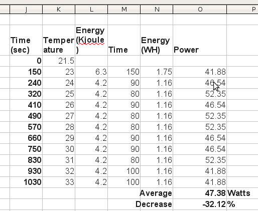
And here is the results that i got out of these measurements:
Before the reflectors, the average power that the water was heated with was 69.8 Watts. After installing these unpolished reflectors, the power reduced down to 47.3 Watts! That is more than 32% decrement! But thats not the end. The reflectors caused a dramatic heat increment above the lamp right on the surface of the acrylic. This means that i will have to decrease the power of the lamp to avoid burning the materials, which in turn means that the power will be even more reduced. Also, i will polish the reflectors which will also increase the heat on the surface. Finally, i plan to install a means of air-flow around the reflectors to avoid heat of the air. Hopefully, after taking all the above measures, i calculate (roughly) that the water cooler will have to dissipate not more than 30 watts with both aluminum profiles. Lets not forget that until now i run the experiments with a single aluminum profile.
Here is the xls file with the calculations and the charts:
The heat was so intense and the reflectors so unpolished, that they got burned with only 17 minutes that the experiment lasted. So, time to make some changes. I'm in the correct path...
Kamenos .... I was introduced Buce %u200B%u200Bof Borneo Indonesia I was very pleased with the files and acrylic glass folding heater at the circuit there is a pic 12F615 microcontroller IC. if I can get the list of programmers, software and downloadernya so I can try if the device can operate ... if Kamenos pleased I could be sent to a file that has been filled in the chip and at what price.
@Charlie i used to use a hot-air gun for bending but believe me, there is no comparison. Unless you make a base which blows equally hot air in a small region.
@Emmanuel the schematic is similar to the circuit that i link to. Very small changes (such as some zerner diodes and staff) are all marked on the new schematic. The parts are labeled on the schematic. Which of the parts are you having problem to clarify?
hallo again sir, i'd like to clarify the bills of requirement. im having troubles about it since you've change the circuitry of the PCB. i was wondering if you could post it as well so i can figure out where and what requirements to use.. im abit confuse on that part... TIA..
wow! thank you very much sir.. this will help me on my bender problems... i'll let you know if it does or does not work.. again thanks.. i'm off shopping for the parts in need.. hehehe!!
@Emmanuel Ah i see what you mean, you want the PCB and the parts layout. Ok, i uploaded them in the 3rd page (http://pcbheaven.com/projectpages/Acrylic_Glass_Folding_Heater/?p=2&topic=worklog)
Keep in mind that:
1. You need to CONFIRM twice that the TRIAC is correctly connected. Check the datasheet of the triac. If it is not correctly placed, then the optocoupler may be damaged.
2. There is LIVE HIGH VOLTAGE on the board. Take super extra precautions, and make sure you've read and understand this first:
http://www.pcbheaven.com/m_pages/el_shock_prec.php
@kammenos Bro im abit confuse on how to translate the diagram, i don't know much about electrical diagrams or how translate it, i just wanted to see/ask the full drawing which i can read, like where these 1 ohm resistor goes to etc. basically a drawing type with labels on it so i can understand which and where to put those capacitors, resistors, diodes etc on full PCB look. like on your worklog page 3 on "electronic staff" you labeled a pic there named "the artwork" for your final PCB design. if i could just have that drawing with labels on it so it would be easy for me to follow through..
@kammenos yeah sure im trying to find out where are the details and the design of your circuit board so that i can create it. i really do need some helping doing this project of mine. so i can use it for my other project.. please do reply.
i've been searching for this kind of bending Machine, and i found it.. i build the same thingy but mine has no cooling type and i can control the heat it produces. i tried looking something to control the amount it gave out, i use a wire from a microwave oven "microme wire" (thats what it is called here in my place). it gives out up to 1500 degrees of heat. i don't know much about circuitry. can you dimmer which can control the amount of heat of the rod will do the same for my "microme wire"? thanks and im looking forward for your reply.
@Miodrag the special glue is a kind of glue that is completely transparent and looks very much alike water. When the glue is poured onto plexiglass, the plastic melts temporary. So, when two plastics are put together under pressure and there is this glue between them, they melt and they join together. When the glue evaporates, they become solids again. The bond is very strong. I do not have the glue bottle, as i was given a small quantity into a glass bottle. But if i find more info i will post it.
But, can You be a little bit specific on what kind of 'special glue' You used and what was the exact procedure for joining those two plexi parts at the end !
Maybe that can be a separate explanation project ? :-)
Hi SoftEe. All materials are listed within the worklog pages. i am not sure about the type of the lamp. actually , it is not lamp, i think it is something like this:
http://www.bltdirect.com/product.php?pid=11052&cat=1913&nm=Infrared+500w+240v+Ceramic+Lamp
The one i have i measured it at 800 Watts, which is super high. If you get yours, get at least half smaller. The dimmer materials are listed on the schematic (click to enlarge). When you finish it, send me images of your design and i will post it in my blog.
At 13 January 2011, 22:20:50 user SoftEe wrote: [reply @ SoftEe]
Impressive! This reminds me when I was in junior high. Pretty much everything electrical I owned I took apart to see if I could improve it or make something different. Do you have a full materials list available? I would love to build one of these for projects around my house. One main project to hide electrical components behind my flat screen TV like this company without having to pay their outrageous prices. HIDEitmounts.com. Following my completion I will post a picture if that's ok. I live a block from a Radio Shack and 1/8 of a mile from a hardware store. I'm thinking this should be pretty straight forward. I'm excited to try it!
Nice thinking.
My grandfather had already made something similar (but simpler) in the 50-s/60-s when plexiglass was still pioneer stuff. Instead of aluminium/water, he used two sheets of asbestos. Instead of a lamp he used 4 resistor wires (3 on bottom, 1 on top) in between the asbestos sheets, where he put the plexi. Operated on 50 volts.
I like your work and way of thinking I though you might have used marble insted of aluminume I think I saw someone do that using thick marble I have no idea what type is that marble but it was thick one anyway keep the good work you did realy great job, I just love it and your site is full of matirials I would come back and sure got it in my feeder.

 Home
Home
 Projects
 Experiments
 Circuits
 Theory
 BLOG
BLOG
 PIC Tutorials
 Time for Science


 Contact
 Forum
Forum
 RSS
RSS


 Water Energy and Cooling Calculations


 Reddit this

