Worklog - Making the reflectors (November 14 2010)
The reflectors i made before was only for test. I had to make some better and more robust reflectors.
I cut 2 new pieces of aluminum foil
With number 600 and 1200 sand papers, i sanded a strip in the middle
Then i brushed this strip to polish it
I made 2 similar pieces
I cut a U aluminum profile, same length as the heater radiator
I trimmed the 2 aluminum foils to the size of the U profiled alu
Now comes the hard part. I had to form the foils into U, and place them inside the aluminum profile. To do this, i used another aluminum tube, smaller than the U profiled alu.
This is the aluminum tube that i used
I wrapped the foil around this tube
And i placed it inside the U profiled
Then i bended the sides around it...
...all the way, until it was fully wrapped
That is the final result
More plumping work
I wanted to run more realistic experiments. So i had to use both aluminum cooling bases. Therefore, i connected them in parallel.
These are the material that i used
I put 2 8mm tubes to the one side of each Y connector
And i connected these ends to the aluminum coolers
That is the final assy.
To maintain proper water flow, i use 10mm diameter tube that is separated into 2 8mm tubes. The separation is done with a Y quick connectors. A same connector is used to join the 2 8mm outputs into one 10mm and return it back to the tank.
Test-run of the reflector
It was time to test my new reflector:
I quickly made some Z-bases to hold it under the lamp
and i placed it there...
The experiment began!
The results of the experiment
I don't think it is necessary to post all numbers and bits of the experiment. Only the results would be enough. After all, you know the procedure from the previous page. So, to my great disappointment, the heat power that needs to be dissipated from the water is is around 120 Watts, which is extremely high...
Complete redisign of the base
After all the previous experiments, i was finally convinced that the lam base was a wrong design from the very first beginning. So i had to re-design it. As i do not know what the final design will be, i made some tests with different designs and materials. Finally, i came to this:
I drilled a hole to both sides of the reflector, about 10mm from the edge
I screwed an L hinge
And i put back the reflector foils
That is the final assy of the reflector
Then i screwed it on a 18mm piece of wood
The bottom side of the reflector is 2mm under the top side of the wood
Had to make the base more steady
I cut 2 more pieces of the same height 18mm wood, about 8cm long
I used lackleim to weld it together
I left it for about 40 minutes
This kind of glue is as strong as cement, with only 5 minutes open time
Now i need of a way to keep the cooling bases into position:
I will use 2 pieces of small U aluminum profile
I drilled a hole right in the middle
This will hold the pieces together
This is the final assy
A slight problem
The final assembly has to be slightly changed. The screw interfere with the radiator's poles. I have an idea how to solve it, but for the time i just moved it slightly to one side.
Last connections
Finally, i had to connect the lamp with the power wires, and also i had to find a way to hold the lamp in position, slightly above the bottom side of the reflector:
I screwed these metallic pieces on each side
The power wires for the radiator goes under these pieces
I connected the lamp to the wires
Ready!
So, i was ready to run the experiment. I hooked everything together:
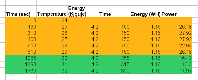
And here are the results
To avoid burning the material, the dimmer was in very low scale. Then, after some tests, i reduced it more. The measurements with the green background (above) were taken when the power was reduced. As yo can see, the water gets about 12 Watts of energy from the lamp, with BOTH the cooling bases installed. So, i think we have a winning design here! I am absolutely convinced that with this design, i will not need any peltier to cool the water. A simple PC fan will be more than enough.
I should also mention that the water temperature during the beginning of the test was about 2 degrees bellow the ambient temperature. Then, when it reached 33 degrees, it did not get any hotter. Why? Because simply, the heat dissipation from the water tank to the air was greater than the heat that it got form the lamp! I suppose that these two magnitudes balanced.
Here are some more photos that i got during the last experiment:
It takes no longer than 3 minutes for the material to be ready to be bended
After each bend, i cooled it with water and immediately done the next bend
I can bend it in very close distances and extreme angles, because the material is heated only in a narrow strip
This is the very first sculpture ever made with my folding heater!
Kamenos .... I was introduced Buce %u200B%u200Bof Borneo Indonesia I was very pleased with the files and acrylic glass folding heater at the circuit there is a pic 12F615 microcontroller IC. if I can get the list of programmers, software and downloadernya so I can try if the device can operate ... if Kamenos pleased I could be sent to a file that has been filled in the chip and at what price.
@Charlie i used to use a hot-air gun for bending but believe me, there is no comparison. Unless you make a base which blows equally hot air in a small region.
@Emmanuel the schematic is similar to the circuit that i link to. Very small changes (such as some zerner diodes and staff) are all marked on the new schematic. The parts are labeled on the schematic. Which of the parts are you having problem to clarify?
hallo again sir, i'd like to clarify the bills of requirement. im having troubles about it since you've change the circuitry of the PCB. i was wondering if you could post it as well so i can figure out where and what requirements to use.. im abit confuse on that part... TIA..
wow! thank you very much sir.. this will help me on my bender problems... i'll let you know if it does or does not work.. again thanks.. i'm off shopping for the parts in need.. hehehe!!
@Emmanuel Ah i see what you mean, you want the PCB and the parts layout. Ok, i uploaded them in the 3rd page (http://pcbheaven.com/projectpages/Acrylic_Glass_Folding_Heater/?p=2&topic=worklog)
Keep in mind that:
1. You need to CONFIRM twice that the TRIAC is correctly connected. Check the datasheet of the triac. If it is not correctly placed, then the optocoupler may be damaged.
2. There is LIVE HIGH VOLTAGE on the board. Take super extra precautions, and make sure you've read and understand this first:
http://www.pcbheaven.com/m_pages/el_shock_prec.php
@kammenos Bro im abit confuse on how to translate the diagram, i don't know much about electrical diagrams or how translate it, i just wanted to see/ask the full drawing which i can read, like where these 1 ohm resistor goes to etc. basically a drawing type with labels on it so i can understand which and where to put those capacitors, resistors, diodes etc on full PCB look. like on your worklog page 3 on "electronic staff" you labeled a pic there named "the artwork" for your final PCB design. if i could just have that drawing with labels on it so it would be easy for me to follow through..
@kammenos yeah sure im trying to find out where are the details and the design of your circuit board so that i can create it. i really do need some helping doing this project of mine. so i can use it for my other project.. please do reply.
i've been searching for this kind of bending Machine, and i found it.. i build the same thingy but mine has no cooling type and i can control the heat it produces. i tried looking something to control the amount it gave out, i use a wire from a microwave oven "microme wire" (thats what it is called here in my place). it gives out up to 1500 degrees of heat. i don't know much about circuitry. can you dimmer which can control the amount of heat of the rod will do the same for my "microme wire"? thanks and im looking forward for your reply.
@Miodrag the special glue is a kind of glue that is completely transparent and looks very much alike water. When the glue is poured onto plexiglass, the plastic melts temporary. So, when two plastics are put together under pressure and there is this glue between them, they melt and they join together. When the glue evaporates, they become solids again. The bond is very strong. I do not have the glue bottle, as i was given a small quantity into a glass bottle. But if i find more info i will post it.
But, can You be a little bit specific on what kind of 'special glue' You used and what was the exact procedure for joining those two plexi parts at the end !
Maybe that can be a separate explanation project ? :-)
Hi SoftEe. All materials are listed within the worklog pages. i am not sure about the type of the lamp. actually , it is not lamp, i think it is something like this:
http://www.bltdirect.com/product.php?pid=11052&cat=1913&nm=Infrared+500w+240v+Ceramic+Lamp
The one i have i measured it at 800 Watts, which is super high. If you get yours, get at least half smaller. The dimmer materials are listed on the schematic (click to enlarge). When you finish it, send me images of your design and i will post it in my blog.
At 13 January 2011, 22:20:50 user SoftEe wrote: [reply @ SoftEe]
Impressive! This reminds me when I was in junior high. Pretty much everything electrical I owned I took apart to see if I could improve it or make something different. Do you have a full materials list available? I would love to build one of these for projects around my house. One main project to hide electrical components behind my flat screen TV like this company without having to pay their outrageous prices. HIDEitmounts.com. Following my completion I will post a picture if that's ok. I live a block from a Radio Shack and 1/8 of a mile from a hardware store. I'm thinking this should be pretty straight forward. I'm excited to try it!
Nice thinking.
My grandfather had already made something similar (but simpler) in the 50-s/60-s when plexiglass was still pioneer stuff. Instead of aluminium/water, he used two sheets of asbestos. Instead of a lamp he used 4 resistor wires (3 on bottom, 1 on top) in between the asbestos sheets, where he put the plexi. Operated on 50 volts.
I like your work and way of thinking I though you might have used marble insted of aluminume I think I saw someone do that using thick marble I have no idea what type is that marble but it was thick one anyway keep the good work you did realy great job, I just love it and your site is full of matirials I would come back and sure got it in my feeder.

 Home
Home
 Projects
 Experiments
 Circuits
 Theory
 BLOG
BLOG
 PIC Tutorials
 Time for Science


 Contact
 Forum
Forum
 RSS
RSS


 Reddit this

