|
 Home Home
 Projects Projects
 Experiments Experiments
 Circuits Circuits
 Theory Theory
 BLOG BLOG
 PIC Tutorials PIC Tutorials
 Time for Science Time for Science
|
| ||
|
PIC Tutorial - A Simple LED Flasher
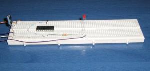 Another simple circuit is the LED flasher. With this tutorial you will become familiar with the delays. It is very important to understand how to generate delays with the PIC. In Action The Circuit 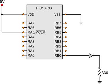
What this circuit does, is to simply flash an LED every half second. To maintain the simplicity of the code, there is no button or other switch conencted to it, as this would be rather off-subject. Bellow is the PIC code of this tutorial. The Code
; RAM preserved -----------------------------------------------------------
	cblock 0x20
		WaitCounter,WaitCounter2
	endc
; Main Program ------------------------------------------------------------
Start
				bank1					;Go to bank 1
				movlw b'11111111'		;
				movwf TRISA				;Set the port pin types of the RA

				movlw b'11111110'		;
				movwf TRISB				;Set the port pin types of the RB
				bank0					;Go to bank 0
MainLoop
				call Wait250mSec
				call Wait250mSec
				bsf PORTB,0				;Set RB0 output
				call Wait250mSec
				call Wait250mSec
				bcf PORTB,0				;Clear RB0 output
				goto MainLoop

Wait250mSec                     movlw d'250'
				movwf WaitCounter2
BackWaitLoop2                   movlw d'163'
                                call WaitWx4Cycle
                                movlw d'163'
                                call WaitWx4Cycles
			        nop
			        nop
			        decf WaitCounter2,f
			        btfss Zero
			        goto BackWaitLoop2
			        return


WaitWx4Cycles                   movwf WaitCounter
BackWaitLoop                    decfsz WaitCounter,f
                                goto BackWaitLoop
                                return
At the end of this tutorial, you will find all the files including the above asm file in one zip to download and test it. The first thing to be noticed is that all ports are inputs except the RB0 port. This is our only output and the LED is connected there. When the program reaches the MainLoop, it calls for a label named 'Wait250mSec'. This label is our calculated 250mSec delay. Twice a call means 1/2 second delay. Now how this delay really work: Go to this label to follow the code. You will notice that the decimal number '250' is loaded to the WaitCounter2 register defined at the beginning of the code. Right after, a 'BackWaitLoop2' label is defined. 8 instructions below, there is this 'goto BackWaitLoop2' instruction. This block, will generate 1mSec delay and will be called as many times as the WaitCounter2 carries, in our occasion that will be 250 times equals to 250mSec. To generate the 1mSec delay, we need to know something about the timing of the PIC. Each instruction cycle needs 4 clock pulses to be implemented. Our PIC is clocked at 4MHz (defined in the OSCCON register within the Init_normal.inc header file). So, if you divide the 4.000.000 Hz by 4, you will get the astonishing number of 1.000.000 instructions per second! Our PIC is capable to execute 1.000.000 instructions per second, and this is our time base to calculate the delay. Follow my thinking: The answer is hidden in plain mathematics. The formula for the above calculation is:
And that means that we need to execute 1000 instructions to generate 1mSec delay. That is the basic idea how to calculate delays. During the intermediate lessons, there will be e fully explanation on how to measure the instruction cycle and delay, because not all instructions have the same cycle. But to avoid all this mess, you can just use the code provided to this tutorial. This will work perfectly for the 4MHz oscillator. It can be used for direct delays from 1mSec to 256mSec. Just load the value in mSec that you want to the WaitCounter2 register and call the BackWaitLoop2 subroutine. If you want more than 256 mSec delay, you can call more than once the same subroutine, as done in this tutorial for the 500mSec (half second) delay. Now, back to the MainLoop. It is most obvious what is done over there. At first, a 500mSec delay is called. Then, the RB0 output is SET, the LED turns on. Afterwards, another 500mSec is called and the RB0 output is CLEARED, the LED is turned off. That keeps going infinitely, and there is your LED flasher! The project Files Following are the files for this project:
Comments
No part of this publication may be reproduced, stored in a retrieval system or transmitted in any form or by any means, electronic, mechanical, photocopying, recording, scanning or otherwise without the prior written permission of the author. Read the Disclaimer
All trademarks used are properties of their respective owners.
Copyright © 2007-2009 Lazaridis Giorgos. All rights reserved. |
  
|
 Contact Contact
 Forum
Projects
Experiments
Circuits
Theory
BLOG
PIC Tutorials
Time for Science Forum
Projects
Experiments
Circuits
Theory
BLOG
PIC Tutorials
Time for Science
 RSS RSS
Site design: Giorgos Lazaridis © Copyright 2008 Please read the Terms of services and the Privacy policy |

 PIC Tutorial - LED Flasher