|
 Home Home
 Projects Projects
 Experiments Experiments
 Circuits Circuits
 Theory Theory
 BLOG BLOG
 PIC Tutorials PIC Tutorials
 Time for Science Time for Science
|
| ||
|
The Data Memory Organization The Data Memory is the part of the PIC that the Special Function Registers and the General Purpose Registers are stored. The Data Memory is divided into 4 banks, each one having 128 bytes length. To access each bank, the RP0 and RP1 bits of the STATUS register needs to be accessed. The following table shows how to select each bank:
For easier bank changing, i have make the following macros that you could paste into your code and use them.
Bank0   macro
        bcf     status,rp1
        bcf     status,rp0        ; BANK0 (Data Memory)
        endm
Bank1   macro
        bcf     status,rp1
        bsf     status,rp0        ; BANK1 (Data Memory)
        endm
Bank2   macro
        bsf     status,rp1
        bcf     status,rp0        ; BANK2 (Data Memory)
        endm
Bank3   macro
        bsf     status,rp1
        bsf     status,rp0        ; BANK3 (Data Memory)
        endm
If you paste the above code, you can then change a bank by it's name. For example, you can switch to bank 1 simply by calling the macro bank1. I have also include the above piece of code in the Microchip header file. If you have download this file from this on-line book, then you have the above macros included as well. This file can be found in previous pages of this book (Creating new files and adding them in the project with the MPLAB. Following, there is a graphic representation of the banks and the registers that each bank carries: 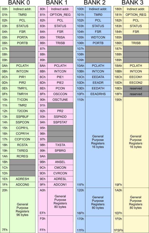
Every register is used for a different job. You may notice that there are some registers, like the PCL and the STATUS register, that exist in more than one bank. This happens for technical reasons, for smaller and faster programs and only. All registers with the same refer to the same one register. There are NO four different PCL registers but on. The goal is that you can refer to this register from any bank you are currently switched to. As you may have understood from the last sentence, to access the registers from a specific bank, you need before to switch to this bank, otherwise the result will be wrong. If for example you wish to access the TRISA register, you need to switch to bank 1 before you access this register. The Special Function Registers These are the named registers shown in the above drawing. Each one of those registers will be explained in details in the following pages of this book. When for example we talk about the I/O ports, the TRIS and PORT registers shall be analyzed. The more comfortable you feel with the SFRs, the more deep you can go with the PIC programming. The General Purpose Registers You may have already notice some regions at the end of each bank with the name 'General Purpose Registers'. This is the place where the user can use to store temporary data. The data stored in the GPRs will be erased after a power on or a reset of the PIC. For permanent data save, the EEPROM memory is used instead. You may consider the GPR as the RAM of the PC The PIC16F88 provides a total of 368 8-bit positions to store your data. You can define your register names at the beginning of your program, before the ORG 0x00 origin of it. There are various ways of declaring your registers: Declaring the registers one by oneYou can declare your registers one by one using the keyword 'equ'. The following code sample will declare 4 different registers at 4 different positions in bank 0: YourRegister1 equ 0x20 YourRegister2 equ 0x21 YourRegister3 equ 0x22 YourRegister4 equ 0x23 Declaring the registers in a block There is another faster way of declaring your registers that i prefer using it. This way uses the block cblock/endc. Within this region, you can declare the registers in series without having to write the position of this register:
        cblock 0x20
                YourRegister1
                YourRegister2
                YourRegister3
                YourRegister4,YourRegister5,YourRegister6,YourRegister7
                YourRegister8:5
        endc
As you see, the block definition is very flexible. First of all, you need to define the beginning of the block. We will store the registers in bank 1, therefore the start should be the 0x20. Then, each time a register is declared, it goes automatically to the next position in memory. This is very helpful when dealing with large mounts of data. Imagine that you have declare 90 different registers and then you find out that there are some registers that you do not really need and you can remove them. If you had declare them with the first way, one by one, then you must remember when adding a new register, that there is free space (from the deleted registers) and you can use it. But with this way, you just delete the register from the block and that's all. And because you can access a register by it's declared name, you do not have to worry about the memory position. Another advantage of this type of declarations is that there are at least three different ways to declare registers. The most obvious is to write the register's name and then go to the next line where you write the next register. This is done in our previous example for the registers 1 through 3. Then, there is another way of doing it. You can declare as many registers as you want in one line separated with a coma, as seen above for registers 4 through 7. Finally, you can declare a begin and length of a series of registers. The registers named 'YourRegister8' in our previous example is not just one registers. The position named YourRegister8 is the beginning of a 5 bytes in series preserved. This way is very helpful when dealing with series of bytes. You can for example declare a 16-byte series with just one line of code: RegisterName:16. Confirm your knowledge There is an online test to check your knowledge on this page. You may reveal the test with the following button: Comments
No part of this publication may be reproduced, stored in a retrieval system or transmitted in any form or by any means, electronic, mechanical, photocopying, recording, scanning or otherwise without the prior written permission of the author. Read the Disclaimer
All trademarks used are properties of their respective owners.
Copyright © 2007-2009 Lazaridis Giorgos. All rights reserved. |
  
|
 Contact Contact
 Forum
Projects
Experiments
Circuits
Theory
BLOG
PIC Tutorials
Time for Science Forum
Projects
Experiments
Circuits
Theory
BLOG
PIC Tutorials
Time for Science
 RSS RSS
Site design: Giorgos Lazaridis © Copyright 2008 Please read the Terms of services and the Privacy policy |