|
 Home Home
 Projects Projects
 Experiments Experiments
 Circuits Circuits
 Theory Theory
 BLOG BLOG
 PIC Tutorials PIC Tutorials
 Time for Science Time for Science
|
| ||
|
Your very first assembly program Hopefully, we have come to this part where all people like: The first program. This first program will be nothing fancy. It would be nice to be a 'Hello World' routine similar to those used for programming tutorials, but it is kinda difficult to be a 'first program' for a PIC micro. The easiest program for me is the one that does absolutely nothing. So, here we go: Opening the file for editing The first 'nothing to do' program must be placed in a source file. This source file is the one created before with the .asm extension. To open the file for editing, you should just boubble-click it in the project explorer. If you have just make this file (from the menu Project -> Add New File to Project...) then this file should be already opened and ready for editing. You should expect to have something like that: 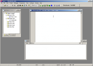
Hands on keyboard It's time to put some code inside. Copy and paste the following code in your assembly source file:
 list       F=inhx8m, P=16F88, R=hex, N=0

#include P16F88.INC ; PIC definitions

 __config _config1,_HS_OSC & _WDT_OFF & _LVP_OFF & _PWRTE_OFF & _MCLR_OFF & _BODEN_ON & _LVP_OFF & _CPD_OFF & _WRT_PROTECT_OFF & _CCP1_RB0 & _CP_OFF

 __config _config2,_IESO_OFF & _FCMEN_OFF

 Errorlevel -302      ; switches off Message [302]: Register in operand not in bank 0.

; Definitions -------------------------------------------------------------

; RAM preserved -----------------------------------------------------------

; Conastants --------------------------------------------------------------

; Program Memory ----------------------------------------------------------

                org     0

                goto    Init

; Interrupt Service Routine -----------------------------------------------

                org     4               ; ISR beginning


; -------------------------------------------------------------------------
; Microcontroller initialization
Init

; Main Program ------------------------------------------------------------

Start

Fins
                end             ; end of program
To save the file, just press Ctrl+S. You should note that this shortcut saves the active file and the active file only!!! The other files, even if they are loaded, as well as the project itself are NOT saved with a simple shortcut! Now, your file should look like that: 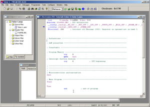
A few words about your first program The first line of code is the 'List' directive. Because at col #1 only labels may be placed, i have pulled this directive one column. The 'L' of the 'List' is placed in column 2 instead of column 1. There is a space before. This should be kept as a rule from you: "In column #1, only labels may start". The List directive defines some characteristics of the program. You should use it as is when dealing with PIC16f88 chips. the second line, is the #include command for the Microchip's PIC16f88 header file. This command tells the compiler to include this file when compiling the program. It is important never to forget this line. Also, you should know that the directory path that this command refers to, is relative to the directory where the assembly file is located. In our case this is the project's directory. If the header file was located in another directory, then the full directory path should be included. The third and fourth lines are the configuration fuses of the chip. Those fuses will determine some characteristics of the PIC like the clock type and source, the protection code, the watchdog timer and many more. We will work on those fuses extensively on further pages. Right now, use them as-is. The fifth line is a directive that will only switch off an annoying warning message. Following there are some comment lines. Those lines start with a semi column. Whatever follows the semi column is considered to be comment and will take no part at all during compilation. You should stick with those comments when making a program. A well commented program is easy to debug and easy to expand. If you make a 1000 lines of uncommented or poor-commented assembly sheet, then it would be almost impossible to debug and/or upgrade this program after a month or so... After a few lines, the 'org 0' directive appears. This tells the compiler that this is program line number #0 and from now on the program starts. Right after is a 'Goto Init' command. This command will place the program pointer to the label named 'Init', a few lines below. The Goto comes from the words Go to, and means exactly this: "Go to line that has the name 'Init'". Under the line labeled 'Init', there is nothing else to be executed, except the 'End' directive. This directive defines the end of program. That's all. The-End. This is a first template for you. You can keep it and use it for writing your programs. Following you will find all files tat the first tutorial consists of to download.
Comments
No part of this publication may be reproduced, stored in a retrieval system or transmitted in any form or by any means, electronic, mechanical, photocopying, recording, scanning or otherwise without the prior written permission of the author. Read the Disclaimer
All trademarks used are properties of their respective owners.
Copyright © 2007-2009 Lazaridis Giorgos. All rights reserved. |
  
|
 Contact Contact
 Forum
Projects
Experiments
Circuits
Theory
BLOG
PIC Tutorials
Time for Science Forum
Projects
Experiments
Circuits
Theory
BLOG
PIC Tutorials
Time for Science
 RSS RSS
Site design: Giorgos Lazaridis © Copyright 2008 Please read the Terms of services and the Privacy policy |
 Tutorial #1 files