|
 Home Home
 Projects Projects
 Experiments Experiments
 Circuits Circuits
 Theory Theory
 BLOG BLOG
 PIC Tutorials PIC Tutorials
 Time for Science Time for Science
|
| ||
|
Instruction Cycle Duration and Calculated Delays What is the relationship between the oscillator frequency of the PIC and the instruction cycle duration? In this page we will discuss about this very important subject. 4 pulses = 1 operation When designing a PIC project, the first thing to consider is the oscillation clock source and frequency of the PIC. In later chapters we will discuss the different clock sources. Until then, the only thing you need to know is that the no matter which input is selected (internal oscillator or external XTAL / RC circuit), we will refer to this input generally as "Clock Input", and the pulses from the Clock Input as "Clock Pulses". The PIC will internally divide the clock input frequency by 4, in order to execute the program instructions. We will name these 4 pulses Q1 through Q4. The Program Counter (more info about the Program Counter) will be increased on every Q1. During these 4 clock pulses, the PIC will fetch the instruction that the updated Program Counter indicates, and simultaneously it will execute the instruction that was fetched during the PREVIOUS Q1-Q4 pulses! This is something that you will probably will never have to deal with, and that will never cause you any further frustration more than understanding how the PIC works. So, look at the following timing chart: 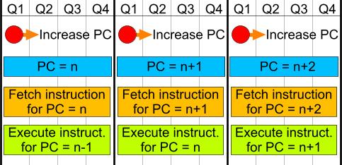
It is clear that the PC (Program Counter) is increased ONCE every 4 clock pulses. This means that every 4 clock cycles, an instruction is executed. But you may also notice, that, for example, in order to execute the instruction in PC position = n+1, the PIC will need 8 clock pulses! During the first 4 pulses, it will fetch the instruction, and during the other 4 pulses it will execute it. This means that the PC will be increased 2 times, but only one instruction will be executed, right? WRONG! This would only happen during the very first instruction that the PIC will execute immediately after the power on. Due to the fact that during Q1-Q4 the PIC does 2 jobs simultaneously (fetch new instruction and execute previous instruction), on every PC increment (4 Clock Pulses) one instruction is executed, or better say that on every PC increment, on operation is carried out. 4 pulses = 1 operation, 1 operation = 1 instruction execution??? The sub-title is of course a rhetorical question. Unfortunately, not all instructions are executed in a single operation (4 clock pulses). There are two categories of instructions that require 2 instruction executions in order to be fulfilled. The first category and most straight-forward to understand contains all the instructions that have a conditional branch. These are the BTFSS, BTFSC, DECSZ and INCSZ (more info for the instructions here). But how is a conditional branch handled from the PIC? Let's see an example with BTFSS instruction:
          BSF Zero    ;We set the Zero Flag
          BTFSS Zero  ;If Zero is SET, then SKIP the next instruction
          {AN INSTRUCTION}
What will happen? On the first instruction, we SET the Zero flag. On the next instruction, we check if the Zero flag is set. The BTFSS means Skip If Set, thus, the following instruction will NOT be executed, as the Zero flag is SET. As a matter of fact, the PIC will NOT jump the following instruction. Instead, it will temporarily convert it into the NOP and will be executed as NOP. In this case, the BTFSS instruction must be calculated as a 2-Cycles instruction, and the instruction that follows the BTFSS must NOT be taken into account! Now look at the following example:
          BCF Zero    ;We set the Zero Flag
          BTFSS Zero  ;If Zero is SET, then SKIP the next instruction
          {AN INSTRUCTION}
This example is the same as the previous one, but now we have CLEAR the Zero flag. The instructions that follows the BTFSS instruction will be executed normally! In this case, the BTFSS instruction must be calculated as an 1-Cycle instruction, and the following instruction must be taken into account accordingly. In other words, the conditional branching instructions may need 1 or 2 instructions cycles to be executed, according to the condition result. This is something that you need to pay attention when calculating the instruction cycles required for a subroutine. The second category with instructions that needs more than 1 cycle to be executed, contains all the instructions that will force the PC to change. These are the GOTO instruction, the CALL and the RETURN (including RETLW and RETFIE). But why does this happen? Well, if you have read and understood the first paragraph (4 pulses = 1 operation), then it will be easy to understand why. In this paragraph i explained that during the very first instruction execution of the program immediately after a power-on, the PIC will require 2 instruction cycles. That is true, but not complete. Whenever the PC is forced (with a GOTO/CALL/RETURN instruction) to change. the PIC will need 2 cycles to execute this instruction. And why is that? Suppose we have this part of code to examine:
          BSF Zero
          MOVLW 0xFF
          GOTO Label_1
          MOVLW b'01010101'
          .
          .
          .
Label_1   MOVWF PORTA
          .
          .
          .
When the PC is on the "MOVLW 0xFF" instruction (line 2), the PIC will execute the "BSF Zero" instruction and will load the "MOVLW 0xFF". On the next instruction cycle, the PC will indicate the "GOTO Label_1" instruction. The PIC will execute the "MOVLW 0xFF" and will fetch the "GOTO Label_1". Here is the interesting part. On the next instruction execution, the PC will indicate the "MOVLW b'01010101'" instruction, and the PIC will execute the "GOTO Label_1" instruction and will fetch the "MOVLW b'01010101'" instruction. On the next instruction cycle, the PC will indicate the instruction right after Label_1, as instructed before from the "GOTO Label_1" instruction. But it will NOT execute the already-fetched instruction, as it is the instruction right after the "GOTO Label_1"! That would be wrong! So, the execution is omitted! The execution of the instructions is then carried out normally by increasing the PC, fetching the new instruction and executing the "MOVWF PORTA" instruction. This execution-cancellation that follows the GOTO command is the reason why such commands requires 2 instruction cycles to be fulfilled. The following table indicates the cycles required from each instruction to be executed:
All other will require 1 instruction cycle to be executed. An example - Calculate an 1 mSec delay subroutine Let's make a real-life example subroutine. This subroutine, will generate an 1 mSec delay. The PIC operates with a 4 MHz clock input. This means that each instruction cycle is executed with 1MHz frequency, in other words, once every 1uSec. So, we need to call a subroutine that will execute 1000 instructions, in order to achieve the 1 mSec delay. Look at the following subroutine:
Delay_1_mSec
          MOVLW d'250'
Delay_Loop
          ADDLW 0xFF       ; Decrease W by 1
          BTFSS Zero       ; Is the Zero flag Set?
          GOTO Delay_Loop  ; - NO. Goto back

          RETURN
The Delay_Loop is composed by 3 instructions, the "ADDLW 0xFF" with 1 cycle duration, the "BTFSS Zero" with 1 cycle duration (as long as W is not 0), and the "GOTO Delay_Loop" with 2 cycles duration. Adding them we have 4 cycles. This loop will be executed 250 times, as the W has the decimal value "250". So, 250 x 4 = 1000! This loop will generate 1000 uSec (that is 1 mSec) delay on each CALL. Here comes some further considerations. The overall delay of the subroutine will NOT be 1000 cycles exactly. It will be precisely 1002 cycles. First of all, we need to add the "MOVLW d'250'" that has 1 cycle length. The loop has 4 cycles overall delay, EXCEPT the last time it loops, that the W wil lbe zero and the "GOTO Delay_Loop" will be replaced with a "NOP" instruction. It will then have 3 cycles overall delay. So, the loop has exactly 249 x 4 + 3 cycles, that is 999 cycles. And finally, we need to add 2 cycles for the return instruction. So we have, 1 + 999 + 2 = 1002 cycles. If someone measures also the 2 cycles from the "CALL Delay_1_mSec" instruction, we have a total of 1004 cycles. How can we fix this? Very easy. I will call the loop (that has 4 cycles duration) one time less:
Delay_1_mSec
          MOVLW d'249'
Delay_Loop
          ADDLW 0xFF       ; Decrease W by 1
          BTFSS Zero       ; Is the Zero flag Set?
          GOTO Delay_Loop  ; - NO. Goto back

          RETURN
Now we have: 248 x 4 + 3 = 995 cycles from the loop, +1 from the "MOVLW d'249'" = 996, +2 from the "RETURN" = 998, +2 from the "CALL Delay_1_mSec", this makes it exactly 1000 instructions! Confirm your knowledge There is an online test to check your knowledge on this page. You may reveal the test with the following button: Comments
No part of this publication may be reproduced, stored in a retrieval system or transmitted in any form or by any means, electronic, mechanical, photocopying, recording, scanning or otherwise without the prior written permission of the author. Read the Disclaimer
All trademarks used are properties of their respective owners.
Copyright © 2007-2009 Lazaridis Giorgos. All rights reserved. |
  
|
 Contact Contact
 Forum
Projects
Experiments
Circuits
Theory
BLOG
PIC Tutorials
Time for Science Forum
Projects
Experiments
Circuits
Theory
BLOG
PIC Tutorials
Time for Science
 RSS RSS
Site design: Giorgos Lazaridis © Copyright 2008 Please read the Terms of services and the Privacy policy |