|
 Home Home
 Projects Projects
 Experiments Experiments
 Circuits Circuits
 Theory Theory
 BLOG BLOG
 PIC Tutorials PIC Tutorials
 Time for Science Time for Science
|
| ||
|
PIC Tutorial - Interfacing Multiple Switches - The internal Pull-Up resistors
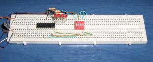 The circuit on a breadboard. The very first tutorial was how to interface a pushbutton. This circuit will interface 4 switches which are able to operate simultaneously 4 different LEDs. Instead of switches you can use pushbuttons as well. The purpose of this tutorial is to become familiar with interfacing switches and pushbuttons and the use of the internal Pull-Up resistors. In Action The circuit 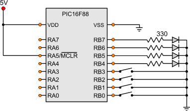
Seeing the circuit, the title of this page starts making sense. Normally, there should be pull-up resistors between the switches and the input pins of the PIC, in our case the ports RB0 through RB3. The circuit above does not contain any pull-up resistor. So, what happens when a switch is not actuated? Is the corresponding pin floating in an unknown state? Actually, no. The PIC 16F88 (and not only) are equipped with internal software-activated pull-up resistors. Those resistors are connected to each one of the 8 ports of the PORT B. They are controlled from the software and can be turned on or off all together from the OPTION_REG register. The bit to control them is the 7th bit and it is a .NOT. bit. This means that if the bit is set, the resistors are NOT enabled. If the bit is 1, the resistors are enabled. For more information about the OPTION)REG registers, see the corresponding page ( The OPTION_REG Register ). The first 4 ports of PORTB (RB0 through RB3) are set as Inputs and the other 4 (RB4 through RB7) are set as Outputs. Each of the PORTB pins has it's own pull-up resistor. The pull-up resistors are only available for the PORTB pins that are set as input. This means that the first 4 PORTB pins do have a pull-up resistor, but the other 4 pins, that are outputs to the LEDs, does NOT have a pull-up resistor enabled. The Code Let's take a look at the code ; Main Program ------------------------------------------------------------ Start bank1 ;Go to bank 1 movlw b'11111111' ; movwf TRISA ;Set the port pin types of the RA movlw b'00001111' ; movwf TRISB ;Set the port pin types of the RB bank0 ;Go to bank 0 bank1 bcf option_reg,NOT_RBPU ;Enable RB Port Pull-Up resistors bank0 MainLoop btfss Switch1 goto Switch_1_Is_0 bcf Output1 goto Check_Switch_2 Switch_1_Is_0 bsf Output1 Check_Switch_2 btfss Switch2 goto Switch_2_Is_0 bcf Output2 goto Check_Switch_3 Switch_2_Is_0 bsf Output2 Check_Switch_3 btfss Switch3 goto Switch_3_Is_0 bcf Output3 goto Check_Switch_4 Switch_3_Is_0 bsf Output3 Check_Switch_4 btfss Switch4 goto Switch_4_Is_0 bcf Output4 goto MainLoop Switch_4_Is_0 bsf Output4 goto MainLoop At the end of this tutorial, you will find all the files including the above asm file in one zip to download and test it. What's interesting to notice in the above code, is how the Pull-Up resistors are enabled. After the PORT type setup, at the beginning of the code, there is this line 'bcf option_reg,NOT_RBPU'. This eill clear the 7th bit of the OPTION_REG register and thus, the pullup resistors shall be enabled for the PORTB pins that are set as inputs. The rest of the code is composed by 4 similar subroutines to check the condition of an input and set the corresponding output accordingly: btfss Switch1 goto Switch_1_Is_0 bcf Output1 goto Check_Switch_2 Switch_1_Is_0 bsf Output1 Check_Switch_2 . . . The first line will check the input pin. If the pin is set, then the program flow will skip the next line and will not execute the following instruction. The next instruction to be executed will clear the corresponding output, and afterwards, a GOTO instruction to the next input check is executed. If the input was NOT set and the next instruction was excecuted, the program flow would GOTO label 'Switch_1_Is_0'. Then, the corresponding output would be SET and the program flow would continue normally to the next input check. You should notice that an output is set when an input is clear. The output is inversed. This is done on purpose because of the pull-up resistors and the type of the switch used. The switches are Normal Open contacts. This means that when they are NOT actuated, the input pin is pulled high due to the pull-up resistors. When the switch is actuated, then the pin is driven low through the switch. You should of course implement the turn-on/off process as will. The project Files Following are the files for this project:
Comments
No part of this publication may be reproduced, stored in a retrieval system or transmitted in any form or by any means, electronic, mechanical, photocopying, recording, scanning or otherwise without the prior written permission of the author. Read the Disclaimer
All trademarks used are properties of their respective owners.
Copyright © 2007-2009 Lazaridis Giorgos. All rights reserved. |
  
|
 Contact Contact
 Forum
Projects
Experiments
Circuits
Theory
BLOG
PIC Tutorials
Time for Science Forum
Projects
Experiments
Circuits
Theory
BLOG
PIC Tutorials
Time for Science
 RSS RSS
Site design: Giorgos Lazaridis © Copyright 2008 Please read the Terms of services and the Privacy policy |

 PIC Tutorial - Interfacing Multiple Switches - The internal Pull-Up resistors