|
 Home Home
 Projects Projects
 Experiments Experiments
 Circuits Circuits
 Theory Theory
 BLOG BLOG
 PIC Tutorials PIC Tutorials
 Time for Science Time for Science
|
| ||
|
Getting familiar with the MPLAB environment At first, you need to get familiar with the MPLAB environment. We need to understand each other when we talk about the regions. The following image shows the MPLAB environment with a loaded project: 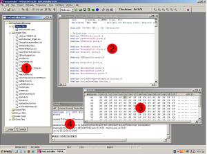
There are 4 basic regions. We will always work on those regions so you need to be able to distinguish them with their names. The first region is the project explorer region, marked with the number 1. Within this region, you will have your files that a project is consisted of. All assembly files and header files are placed in this region. When you need to edit one project file, you find it there and double click it. The second region, marked with the number 2, is the code window. In this window, you will be able to see and edit the code of a project file. The third region with number 3 on it, is the EEPROM window. In this region, you will be able to see, download, change and upload the PIC EEPROM memory. You can also save multiple memory paterns on the PC HDD. The EEPROM is only uploaded to the PIC after request or if you set a specific option. You should pay attention when working with this area. When an MPLAB project is loaded, the EEPROM window is filled with 0xFF hex value, no matter what was the last memory pattern you had saved. This may give you a headache as on the next program upload, if you have set the option to upload the EEPROM memory as well, the PIC EEPROM area shall be erased and you may get some unpredictable and funny results. The fourth area, is the output window. All messages that follow a project build (compile and linking) and PIC upload/download procedures, as well as communication with the programmer, are shown in this area. When building a project, you should always check if you had errors or warnings. If not, you may search for the "ghost" that prevents your code to work. A warning that a value has exceeded the maximum length is a very common "ghost"... But what is an MPLAB project anyway? When you start programming PICs in assembly, you will notice that there will be some major sheets of code. The 16F88 basic header file for example, provided from Microchip, is 350 lines of code, and needs always to be included "as is" within your code. Therefore, we choose to make external inclusion files (with the extension .icn). Those files will be included with the #include command within the assembly code. This command will be explained in details later on. During the linking procedure, the code that exists in those inc files, will be placed in the assembly listing, at the position where the #include command is. But during developing time, they will be in separated files. Two major advantages come along with this feature. At first, the most obvious is the ease of programming. You will have to handle small parts of code instead of searching within hundreds and hundreds of assembly listing lines. As time passes, you will develop your own "separating policy". Keep in mind that you should separate the files in such a way that each file should keep a complete routine. Do not over-separate them, as you will reach the other edge. The other advantage is that you can make object files that are used in many projects as-is with the same functionality. This will boost up your programming skills and will reduce the time required significantly. For example, i have make an inc file named "mSecDelay16MHz.inc". This file has some routines that creates from one to 250 mSec time delay in PICs where i use 16MHz crystal oscillator. The next time that i will need to make for example 0.5 Sec delay (e.g for LED blinking), i will just #include this file and i will call the 250mSecDelay routine twice. That's it! I have also make more complicated routines, such as for example a complete LCD serial communications and more. I will gradually upload all of those routines, fully commented. Comments
No part of this publication may be reproduced, stored in a retrieval system or transmitted in any form or by any means, electronic, mechanical, photocopying, recording, scanning or otherwise without the prior written permission of the author. Read the Disclaimer
All trademarks used are properties of their respective owners.
Copyright © 2007-2009 Lazaridis Giorgos. All rights reserved. |
  
|
 Contact Contact
 Forum
Projects
Experiments
Circuits
Theory
BLOG
PIC Tutorials
Time for Science Forum
Projects
Experiments
Circuits
Theory
BLOG
PIC Tutorials
Time for Science
 RSS RSS
Site design: Giorgos Lazaridis © Copyright 2008 Please read the Terms of services and the Privacy policy |