|
 Home Home
 Projects Projects
 Experiments Experiments
 Circuits Circuits
 Theory Theory
 BLOG BLOG
 PIC Tutorials PIC Tutorials
 Time for Science Time for Science
|
| ||
|
PIC Tutorials - An LED Sequencer
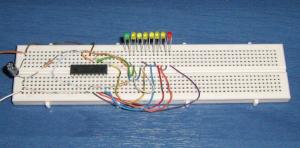 The circuit on a breadboard. This tutorial will demonstrate an LED sequencer. The LEDs will turn on one after another from right to left. With this tutorial you will become familiar with the bit rotate function. In Action The Circuit 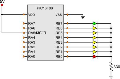
One remark needs to be done for the above circuit. There is only one limiting resistor for all 8 LEDs. Normally this would be wrong. A limiting resistor should be added to each LED separately to ensure the same brightness for all the LEDs no matter how many are turned on. But because only one LED is turned on each time, there is no need for separated resistors. The Code Let's take a look at the code ; Main Program ------------------------------------------------------------ Start bank1 ;Go to bank 1 movlw b'11111111' ; movwf TRISA ;Set the port pin types of the RA movlw b'00000000' ; movwf TRISB ;Set the port pin types of the RB bank0 ;Go to bank 0 MainLoop bcf Carry call Wait500mSec clrf PORTB bsf PORTB,0 ;Set RB0 output call Wait500mSec rlf PORTB,f call Wait500mSec rlf PORTB,f call Wait500mSec rlf PORTB,f call Wait500mSec rlf PORTB,f call Wait500mSec rlf PORTB,f call Wait500mSec rlf PORTB,f call Wait500mSec rlf PORTB,f goto MainLoop This is a rather simple code. First, we set all the RB pins as outputs. Then the MainLoop is continuously looped. 9 steps are within this loop:
When all steps are done, the loop will run again from the beginning. Notice the 'call Wait500mSec' instruction between each step. This instruction will create a 500 mSec delay. The subroutine 'Wait500mSec' is located inside the header file 'mSecDelays4MHz.inc' that is included in the project. As always, all files needed for this project can be found at the bottom of the page. The project Files Following are the files for this project:
Comments
No part of this publication may be reproduced, stored in a retrieval system or transmitted in any form or by any means, electronic, mechanical, photocopying, recording, scanning or otherwise without the prior written permission of the author. Read the Disclaimer
All trademarks used are properties of their respective owners.
Copyright © 2007-2009 Lazaridis Giorgos. All rights reserved. |
  
|
 Contact Contact
 Forum
Projects
Experiments
Circuits
Theory
BLOG
PIC Tutorials
Time for Science Forum
Projects
Experiments
Circuits
Theory
BLOG
PIC Tutorials
Time for Science
 RSS RSS
Site design: Giorgos Lazaridis © Copyright 2008 Please read the Terms of services and the Privacy policy |

 PIC Tutorials - An LED Sequencer