|
 Home Home
 Projects Projects
 Experiments Experiments
 Circuits Circuits
 Theory Theory
 BLOG BLOG
 PIC Tutorials PIC Tutorials
 Time for Science Time for Science
|
| ||
|
PIC Tutorials - Interface a Single 7seg Digit
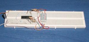 The circuit on a breadboard The most common and easiest way of number (and in some case letters) visualization is to use the classic 7-seg LED displays. Those displays have 7 different LEDs in their package. Combining the LEDs (segments) that will light, numbers and letters can be visualized. This circuit will visualize the numbers from 0 to 9. In Action The Circuit The schematic circuit is as follows: 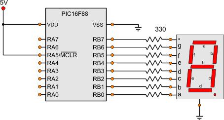
The Code The code is shown bellow: ; Main Program ------------------------------------------------------------ Start bank1 ;Go to bank 1 movlw b'11111111' ; movwf TRISA ;Set the port pin types of the RA movlw b'00000000' ; movwf TRISB ;Set the port pin types of the RB bank0 ;Go to bank 0 MainLoop movlw b'00111111' ;Number 0 movwf PORTB call Wait500mSec movlw b'00000110' ;Number 1 movwf PORTB call Wait500mSec movlw b'01011011' ;Number 2 movwf PORTB call Wait500mSec movlw b'01001111' ;Number 3 movwf PORTB call Wait500mSec movlw b'01100110' ;Number 4 movwf PORTB call Wait500mSec movlw b'01101101' ;Number 5 movwf PORTB call Wait500mSec movlw b'01111101' ;Number 6 movwf PORTB call Wait500mSec movlw b'00000111' ;Number 7 movwf PORTB call Wait500mSec movlw b'01111111' ;Number 8 movwf PORTB call Wait500mSec movlw b'01101111' ;Number 9 movwf PORTB call Wait500mSec goto MainLoop As always, we set the pin types first. All RB pins are outputs, as they are connected on the 7-seg. Then, a series of binary bytes are sent to the PORTB. Each binary byte will correspond to a number. For example let's take a look at number '0'. For visualizing number '0' on the 7-seg, the segments a,b,c,d,e and f should light. From the schematic diagram it can be seen that segment 'a' is conencted to RB0, segment 'b' to RB1, segment 'c' to RB2 and so on. Now it makes sense. To visualize number '0',we send the binary number b'00111111'. For number '1', we send the binary number b'00000110' and so on. Between each number, a 'call Wait500mSec' instruction is executed. This instruction will call a subroutine that will make a 500 mSec delay. So the numbers will change with half a second delay. This subroutine is inside the header file 'mSecDelays4MHz.inc'. As always, all files needed for the project can be found at the bottom of the page. The project Files Following are the files for this project:
Comments
No part of this publication may be reproduced, stored in a retrieval system or transmitted in any form or by any means, electronic, mechanical, photocopying, recording, scanning or otherwise without the prior written permission of the author. Read the Disclaimer
All trademarks used are properties of their respective owners.
Copyright © 2007-2009 Lazaridis Giorgos. All rights reserved. |
  
|
 Contact Contact
 Forum
Projects
Experiments
Circuits
Theory
BLOG
PIC Tutorials
Time for Science Forum
Projects
Experiments
Circuits
Theory
BLOG
PIC Tutorials
Time for Science
 RSS RSS
Site design: Giorgos Lazaridis © Copyright 2008 Please read the Terms of services and the Privacy policy |

 PIC Tutorials - Interface a Single 7seg Digit